


21
MOTOR SELECTION
ELDOM24 3/4M-6M
CURRENT SENSOR
LEVEL 1...5
LIMITED OPENING
SETTING 1...9
Arrow
to scroll
TEST FS
ON/OFF
INSTALLED BOOM
LEFT/RIGHT
MEMO RADIO
ON/OFF
“PROG/OK”
to change
the value
“PROG/OK”
to change
the value
“PROG/OK”
to change
the value
“PROG/OK”
to change
the value
“PROG/OK”
to confirm
“PROG/OK”
to change
the value
RESET PARAMETERS
OK
FW VERSION
ELDOM24 V0.04
EXIT
“PROG/OK”
per ritornare al
menu moto
MOTOR SELECTION
ELDOM24 3/4M-6M
CURRENT SENSOR
LEVEL 1...5
BRAKING CLOSING
SETTING 1...9
MOTOR SELECTION
ELDOM24 3/4M-6M
CURRENT SENSOR
LEVEL 1...5
CLOSING BRAKING
SETTING 1...9
“PROG/OK”
to change
the value
CURRENT SENSOR
LEVEL 1...5
CLOSING BRAKING
SETTING 1...9
CLOSING DECELER.
SETTING 1...9
“PROG/OK”
to change
the value
CLOSING BRAKING
SETTING 1...9
CLOSING DECELER.
SETTING 1...9
OPENING DECELER.
SETTING 1...9
DIST. FROM OPEN
STEPS 1...9
CLOSING SPEED
LEVEL 1...3
PAUSE TIME
130 SEC.
“PROG/OK”
to change
the value
Note: 6
Note: 8
Note: 7
CLOSING SPEED
LEVEL 1...3
PAUSE TIME
180 SEC.
RESET PARAMETERS
OK.
“PROG/OK”
to confirm
* * * * * * * * * * * * * * *
* *
*
PAUSE TIME
*
*
SEC.
*
* *
* * * * * * * * * * * * * * *
180
“PROG/OK”
to confirm
Press the arrows
to increase or
decrease the value
(max. 240 seconds).
Keeping the arrows
held down will force
the value to scroll
rapidly.
CLOSING DECELER.
SETTING 1...9
OPENING DECELER.
SETTING 1...9
DIST. FROM CLOSE
STEPS 1...9
SLOWING IN OPENING
SETTING 1...9
DIST. FROM CLOSE
STEPS 1...9
DIST. FROM OPEN
STEPS 1...9
DIST. FROM CLOSE
STEPS 1...9
DIST. FROM OPEN
STEPS 1...9
CLOSING SPEED
LEVEL 1...3
PAUSE TIME
180 SEC.
RESET PARAMETERS
OK
FW VERSION
ELDOM24 V0.04
Note: 10
OPTIONS
SAFETY DEVICES
MOTION
DISPLAY
CALENDAR
REMOTE
PROGRAM
TB FI
FS CP
TA TD
TC
00.000.007
OPTIONS
SAFETY DEVICES
MOTION
DISPLAY
CALENDAR
REMOTE
Arrow
to scroll
SEQUENTIAL COM.
OPEN-SHUT/
OPEN-STOP-SHUT
AUTO. RECLOSING
ON/OFF
PRE-FLASHING
ON/OFF
OPTIONS
SAFETY DEVICES
MOTION
DISPLAY
CALENDAR
REMOTE
Arrow
to scroll
SEQUENTIAL COM.
OPEN-SHUT/
OPEN-STOP-SHUT
AUTO. RECLOSING
ON/OFF
PRE-FLASHING
ON/OFF
SEQUENTIAL COM.
OPEN-SHUT/
OPEN-STOP-SHUT
AUTO. RECLOSING
ON/OFF
PRE-FLASHING
ON/OFF
AUTO. RECLOSING
ON/OFF
PRE-FLASHING
ON/OFF
WARNING LIGHTS
FIXED/
INTERMITTENT
WARNING LIGHTS
FIXED/
INTERMITTENT
BOOM LIGHTS
FIXED/
INTERMITTENT
PHOTOCELL INVERT
DURING CLOSING/
AND IN STOP
BOOM LIGHTS
FIXED/
INTERMITTENT
PHOTOCELL INVERT
DURING CLOSING/
AND IN STOP
TEST FI
ON/OFF
PHOTOCELL INVERT
DURING CLOSING/
AND IN STOP
TEST FI
ON/OFF
TEST FS
ON/OFF
TEST FI
ON/OFF
TEST FS
ON/OFF
INSTALLED BOOM
LEFT
“PROG/OK”
to confirm
“PROG/OK”
to change
the value
“PROG/OK”
to change
the value
“PROG/OK”
to change
the value
“PROG/OK”
to change
the value
“PROG/OK”
to change
the value
“PROG/OK”
to change
the value
“PROG/OK”
to change
the value
“PROG/OK”
to change
the value
CONTACT TB
NC/8K2
CONTACT FI
NC/8K2
CONTACT FS
NC/8K2
CONTACT TB
NC/8K2
CONTACT FI
NC/8K2
CONTACT FS
NC/8K2
“PROG/OK”
to confirm
“PROG/OK”
to change
the value
“PROG/OK”
to change
the value
CONTACT TB
NC/8K2
CONTACT FI
NC/8K2
CONTACT FS
NC/8K2
“PROG/OK”
to change
the value
CONTACT FI
NC/8K2
CONTACT FS
NC/8K2
CONTACT CP
NC/8K2
“PROG/OK”
to change
the value
CONTACT FS
NC/8K2
CONTACT CP
NC/8K2
EXIT
“PROG/OK”
to return to
‘safety devices’
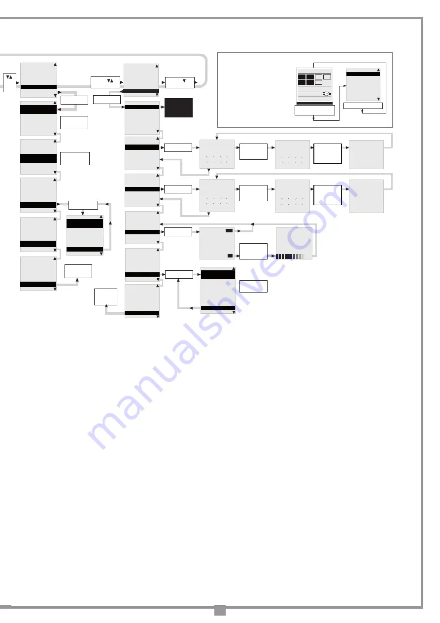
Note: 1
Note: 2
The number of
manoeuvres
carried out by
the barrier and
the time and
date are
always shown
on the opening
screen of the
display.
The plug
symbol
indicates that the
ECU is working
off mains power.
The fully
charged battery
symbol
indicates that the
ECU is working
off battery power
at 100%.
75%
50%
25%
0%
Press an arrow
key to enter the
main menu
PRE-FLASHING
ON/OFF
WARNING LIGHTS
FIXED/
INTERMITTENT
BOOM LIGHTS
FIXED/
INTERMITTENT
“PROG/OK”
to change
the value
07-06-13 15.35
“PROG/OK”
to confirm
Press the arrows
to increase or
decrease the value
(max. 63)
* * * * * * * * * * * * * * *
* *
* SET CONTRAST *
* SEC. *
* *
* * * * * * * * * * * * * * *
26
OPTIONS
SAFETY DEVICES
MOTION
DISPLAY
CALENDAR
REMOTE
CONTRAST
0....63
REAR LIGHTING
ALWAYS ON/60/30 SEC.
EXIT
“PROG/OK”
to confirm
CONTRAST
0....63
REAR LIGHTING
ALWAYS ON/60/30 SEC.
EXIT
“PROG/OK”
to change
the value
CONTRAST
0....63
REAR LIGHTING
ALWAYS ON/60/30 SEC.
EXIT
“PROG/OK”
to return to
‘display’
“PROG/OK”
to change
the value
OPTIONS
SAFETY DEVICES
MOTION
DISPLAY
CALENDAR
REMOTE
Arrow
to
scroll
SET TIME
08:00
SET DATE
23-12-13
SET EVENTS
SET TIME
08:00
SET DATE
23-12-13
SET EVENTS
“PROG/OK”
to change
the value
SET TIME
08:00
SET DATE
23-12-13
SET EVENTS
“PROG/OK”
to confirm
“PROG/OK”
to confirm
EVENT 0
MO-SU 08-10 TA 1
EVENT 1
MO-SU 08-10 TA 1
EVENT 2
MO-FR 10-08 TA 0
EXIT
SET DATE
23-12-13
SET EVENTS
EVENTS: ON/OFF
SET EVENTS
EVENTS: ON/OFF
EXIT
“PROG/OK”
to confirm
PRESS the
transmitter
channel
to memorise
PRESS the
the same
transmitter
channel
again
“PROG/OK”
to confirm
Arrow
to scroll
ENCODING: S4XX
MEMORISE
CANCEL
CLEAR ALL MEMORY
CHANNEL FUNCTION
EXIT
“PROG/OK”
to confirm
OPTIONS
SAFETY DEVICES
MOTION
DISPLAY
CALENDAR
REMOTE
MEMORISE
[Nr...]
* * * * * * * * * * * * * * *
* *
* ACTIVATION 1 *
* *
* * * * * * * * * * * * * * *
MEMORISE
[Nr...]
* * * * * * * * * * * * * * *
* *
* ACTIVATION 2 *
* *
* * * * * * * * * * * * * * *
MEMORISE
[Nr...]
* * * * * * * * * * * * * * *
* *
* CODE *
* MEMORISED *
* * * * * * * * * * * * * * *
“PROG/OK”
to confirm
CANCEL
[Nr...]
* * * * * * * * * * * * * * *
* *
* ACTIVATION 1 *
* *
* * * * * * * * * * * * * * *
PRESS the
transmitter
channel
to memorise
CANCEL
[Nr...]
* * * * * * * * * * * * * * *
* *
* ACTIVATION 2 *
* *
* * * * * * * * * * * * * * *
PRESS the
the same
transmitter
channel
again
CANCEL
[Nr...]
* * * * * * * * * * * * * * *
* *
* CODE *
* CANCELLED *
* * * * * * * * * * * * * * *
ENCODING: S4XX
MEMORISE
CANCEL
CLEAR ALL MEMORY
CHANNEL FUNCTION
EXIT
“PROG/OK”
to confirm
* * * * * * * * * * * * * * *
* CANCEL *
* ALL MEMORY ?*
* * * * * * * * * * * * * * *
PRESS ok to
cancel all
memory
or press exit
ENCODING: S4XX
MEMORISE
CANCEL
CLEAR ALL MEMORY
CHANNEL FUNCTION
EXIT
Arrow
to exit
EXIT
OK
* * * * * * * * * * * * * * *
* CANCELLING *
* * * * * * * * * * * * * * *
ENCODING: S4XX
MEMORISE
CANCEL
CLEAR ALL MEMORY
CHANNEL FUNCTION
EXIT
CHANNEL A
channel function A
CHANNEL
B
channel function B
CHANNEL C
channel function C
CHANNEL D
channel function D
EXIT
ENCODING: S4XX
MEMORISE
CANCEL
CLEAR ALL MEMORY
CHANNEL FUNCTION
EXIT
“PROG/OK”
to change
the value
ENCODING: S4XX
MEMORISE
CANCEL
CLEAR ALL MEMORY
CHANNEL FUNCTION
EXIT
“PROG/OK”
to toggle the
value between
S4XX & S500
“PROG/OK”
to return to
the remote
menu
[AB--]
[AB--]
[AB--]
[AB--]
[AB--]
[AB--]
ITALIANO
FRANÇAIS
ENGLISH
NEDERLANDS
DEUTSCH
ESPAÑOL
PROGRAM
TB FI
FS CP
TA TD
TC
00.000.007
07-06-13 15.35
press both arrows
simultaneously to enter
the language submenu
“PROG/OK” to confirm
• Press the right and left buttons
simultaneously to enter the
language submenu.
• Press the right and left buttons
to change the language: Italian
to English.
• Press the "PROG/OK" button
to confirm the choice.
Language choice:
Note: 13
Note: 12
“PROG/OK”
to return to the
calender menu
Note: 11
Note: 9
INSTALLED BOOM
LEFT/RIGHT
MEMO RADIO
ON/OFF
ERR 230V BOOM UP
ON/OFF
MEMORADIO
ON/OFF
ERR 230V BOOM UP
ON/OFF
RAPID RECLOSING
ON/OFF
“PROG/OK”
to change
the value
“PROG/OK”
to change
the value
Note: 4
Note: 3
“PROG/OK”
to return to
‘options’
ERR 230V BOOM UP
ON/OFF
RAPID RECLOSING
ON/OFF
AUX1 - AUX2
CH2 / CRTY LIGHT
RAPID RECLOSING
ON/OFF
AUX1 - AUX2
CH2 / CRTY LIGHT
EXIT
“PROG/OK”
to change
the value
Note: 5
• Set the main operating parameters (e.g. installation right/left) in the options menu.
• If you have safety devices working with 8.2k contacts select the correct setting from the safety device menu.
• Before programming the boom travel distances select the correct motor in the "Motion" menu.
5) Aux1 - Aux2:
- closed / open -
aux 1
= closed barrier signal -
aux 2
= open barrier signal;
- ch2 / courtesy light -
aux 1
= enables the second channel by radio -
aux 2
= contact for courtesy light;
- closed / courtesy light -
aux 1
= closed barrier signal -
aux 2
= courtesy light.
6) Setting the current sensor:
-
Level 1
= motor input +
2
amps
-
Level 2
= motor input +
3
amps
-
Level 3
= motor input +
4
amps
-
Level 4
= motor input +
5
amps
-
Level 5
= motor input +
6
amps
When the sensor is activated the boom immediately reverses movement for approx.
10 cm
, whether it was opening or closing, so that the obstacle
is freed; it then remains at a standstill for
3 minutes
,after which there is a pre-blinking stage of
10 seconds
before the boom starts moving again in
the same direction as when movement was interrupted.
7) Braking when closing:
Normalmente il valore di default "
2
" impostata in fabbrica soddisfa quasi tutti i casi. When the boom is closing, it decelerates noticeably just a few
degrees before gently ending the manoeuvre. The parameter controls the distance from the closing stop point at which this deceleration occurs. The
value "
9
" means that the final deceleration starts well before the closing stop point. The factory-set default value of "
2
" normally satisfies almost all
situations
8) Deceleration in closing / opening:
These 2 parameters control the starting point for the boom deceleration. A higher number means more space for slowing down, whereas a lower
number means less space. Before starting a movement, check the spring is balanced since the default values are calibrated for best movement
9) Setting the distance from the closing/opening stop point:
To increase or decrease this distance, set the parameter to anywhere between 0 and 9. Set at "
0
",the boom will stop very near the stop point, at "
9
"
the boom will stop further away from the stop point.
10) Closing speed:
The parameter controls the overall closing speed, "
1
" = max. speed "
2
" = med. speed "
3
" = min. speed
11) On/Off events:
By setting the On/Off function on one of the radio channels, it is possible to activate/deactivate the events by remote control. Activation is indicated
by the flashing light blinking for 6 seconds and by the warning light. Deactivation is indicated by the light blinking for 3 seconds.
12) Coding:
Before changing the type of coding
, it is necessary to change the storage module from
S4XX
to
S500
or vice versa, having first cut off the
electricity supply to the control unit.
13) Channel functions
Each radio control channel can
be
"
A
","
B
","
C
","
D
" set to one of
7 available functions:
-
TD
sequential command
-
TA
open
-
TC
close
- Block
-
CH2
second radio channel
- events on/off


