background image

22

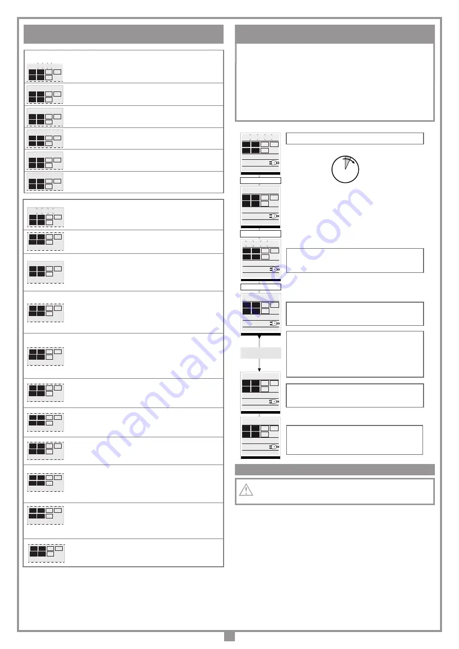
PROGRAMMING PROCEDURE

(boom travel distance and current sensor)

• 

The installation of anti-derailment buffers is 

absolutely obligatory

.

• Before programming set the main operating parameters in the "OPTIONS" 

menu.

• It is not possible to enter programming when working off battery power.
• Make sure the safety devices are at rest and the ECU is receiving mains power 

otherwise you will not be able to enter programming. 

• 

Attention:

 The cover microswitch is an 

NC

 security contact and must be  held 

down continuously during programming (detail 5, fig. 9).

REPOSITIONING

Attention!

 During the repositioning manoeuvre the current sensor value 

could be altered. At the end of the manoeuvre, however, it will reset 
automatically to the chosen value.

 If the programmer blocks due to an encoder count error ("Error ENC" on the dis-
play), after a programmer reset ("Out of pos."), when the motor has been released 
("Released motor") or there is a problem with the motor ("Mot error") the warning 
lights and indicator light will flash simultaneously for 

2 seconds

 and will then switch 

off for 

10 seconds

If in this stage you send a (

TA, TC 

or

 TD

) command to the programmer.

The programmer will move the boom slowly  to the completely closed position (2 
times as in the programming procedure) in order to recover the correct position.
At this point the programmer will function normally. If a "

TA

" command is given the 

positioning recovery is carried out in the opening direction.
No commands will be accepted during repositioning but the security devices will cut 
in and block all movement if they go into alarm.
To interrupt the repositioning manoeuvre press the "

PROG

" or "

TB

" button.

1...4... sec.

The pause time count will start (

min. 2 seconds: max. 240 

seconds

) indicated by "

PAUSE

" and the elapsed time 

appearing on the display

Press “

PROG

” to set the pause time to the required value. The 

boom will now open slowly in order to find the completely open 

position. 

When the boom reaches the completely open travel limit it will invert 

the travel direction and after moving a few centimetres it will open 

again to confirm the completely open position. At this point the 

boom will start to close. When the boom reaches the completely 

closed travel limit it will invert the travel direction and after moving a 

few centimetres it will close again to confirm the completely closed 

position. 

After carrying out this manouvre the control logic will carry out a 

complete opening and closing cycle at the standard operating 

speed in order to calibrate the current sensor.

When the boom reaches the completely closed position the 

programmer saves the parameters and quits the 

programming mode. The operation has not succeeded. You 

will have to repeat the programming procedure

.

Press and hold down prog/ok for 4 seconds

“PROG/OK” for 4 sec.

AUTOMATIC

PROGRAMMING CYCLE

PROGRAM

TB FI
FS CP

TA TD

TC

00.000.007
07-06-13   15.35

“PROG/OK” 

PAUSE

TB FI
FS CP

TA TD

TC

00.000.007
07-06-13   15.35

AUTO PROG.

“PROG/OK” 

TB FI
FS CP

TA TD

TC

00.000.007
07-06-13   15.35

AUTO PROG.

OPENING

TB FI
FS CP

TA TD

TC

00.000.007
07-06-13   15.35

AUTO PROG.

 CLOSING

TB FI
FS CP

TA TD

TC

00.000.007
07-06-13   15.35

AUTO PROG.

PROGRAM

TB FI
FS CP

TA TD

TC

00.000.007
07-06-13   15.35

PAUSA

[030]

Flashing on the display. You have to enter the programming mode to 

program the system. 

During normal operation it indicates that the "automatic repositioning" 
procedure is about to take place. In this case any commands received 
(

TA, TC, or TD

) will automatically start this procedure.


This happens when an N.C. contact is activated (

FI, FS, CP

) during 

encoder programming or automatic repositioning. Once the passive 
state of the security devices has been reset the boom will start moving 
again automatically. It also happens if a blackout occurs during 
programming.

Safety device test error. Check the condition of the safety devices and 
make sure that the alarm cuts in when an obstacle interferes with the 
beam (indication white characters on a black background). In case of 
anomalies replace the damaged safety device or bridge the contact 
and deactivate the safety test  (option menu).

This occurs when the programmer sends a command to the motor and 
nothing happens (motor  doesn't move). Check the connections of the 
motor and the condition of the fuses "

F1

", "

F3

" and then give another 

opening or closing command. If the motor still doesn't move you are 
faced with either a mechanical problem or a problem with the 
programmer. 

Encoder count error. If this error occurs during normal motor operation 
it means that there is a problem with the encoder signal. Check the 
relative connections and carry out automatic repositioning.

Encoder direction error. The boom movement direction is different 
from the encoder setting (eg. the boom moves in the closing direction 
while the program is carrying out the opening stage). Check motor  
power supply connections.

Current sensor error. When the boom is not moving this symbol means 
there is a problem with the current sensor.

When the  safety edge intervenes the boom will automatically invert 

for a few moments, both in the closing as well as the opening 

direction, to free the obstacle it will then stop for 3 minutes and then 

continue moving in the original direction after a 10 second preflashing 

period has elapsed.
When the sensor intervenes the boom will automatically invert for a 

few moments, both in the closing as well as the opening direction, to 

free the obstacle it will then stop for 3 minutes and then continue 

moving in the original direction after a 10 second preflashing period 

has elapsed.

Motor freed indication. When the motor has been reset and a 

command has been received an automatic repositioning cycle will be 

carried out. 

Alarm indications

TB FI
FS CP

TA TD

TC

PROGRAM

TB FI
FS CP

TA TD

TC

OUT OF POSITION

TB FI
FS CP

TA TD

TC

SAFETY ERROR

TB FI
FS CP

TA TD

TC

STOP PROG

AUTO PROG

TB FI
FS CP

TA TD

TC

MOTOR ERROR

TB FI
FS CP

TA TD

TC

ENCODER ERROR

TB FI
FS CP

TA TD

TC

DIRECTION ERROR

TB FI
FS CP

TA TD

TC

SENSOR ERROR

TB FI
FS CP

TA TD

TC

ACT. SAFETY ADGE

TB FI
FS CP

TA TD

TC

ACTIVE SENSOR

Pause time programming or pause for automatic reclosing (if 

activated)

Automatic programming under way

Opening stage

Block during opening   

Closing stage

Block during closing 


Operational indications

TB FI
FS CP

TA TD

TC

PAUSE

TB FI
FS CP

TA TD

TC

AUTO PROG

TB FI
FS CP

TA TD

TC

OPENING

TB FI
FS CP

TA TD

TC

STOP OPENING

TB FI
FS CP

TA TD

TC

CLOSING

TB FI
FS CP

TA TD

TC

  STOP CLOSING

TB FI
FS CP

TA TD

TC

MOT. FREED

OPERATING AND ALARM INDICATIONS

Summary of Contents for ELDOM34DG

Page 1: ...ostruttrice la quale ne ha verificato la perfetta corrispondenza delle caratteristiche con quelle richieste dalla normativa vigente This product has been tried and tested in the manufacturer s laboratory who have verified that the product conforms in every aspect to the safety standards in force Ce produit a été testé et essayé dans les laboratoires du fabricant Pour l installer suivre attentiveme...

Page 2: ...CLATURE 1 Barrière 2 Sélecteur à clé 3 Cellule photoélectrique 4 Interrupteur omnipolaire ouverture des contacts min 3 mm 5 Senseur magnétique 6 Lisse standard 7 Programmateur 8 Clignoteur 9 Lyre de repos 10 Profil en caoutchouc ZEICHENERKLÄRUNG 1 Schranke 2 Schlüsselschalter 3 Lichtschranken 4 Allpoliger Schalter mit einem Kontaktenabstand von 3 mm 5 Induktionsschliefe 6 Standard Schlagbaum 7 Ste...

Page 3: ...ALLATION FIXATION DE LA LISSE À GAUCHE BEFESTIGUNG DES SCHLAGBAUMS AUF DER LINKEN SEITE FIJACIÓN DE LA BARRA A LA IZQUIERDA 4 30 30 30 F 30 BASEDOM6 Contropiastra di fissaggio opzionale Ground fastening base optional Contre plaque de fixation en option Befestigungs Grundplatte extra Contraplaca de fijación opcional 3 6 5 H G 231 Installazione a pavimento senza contropiastra Pavement installation w...

Page 4: ...4 INSTALLAZIONE ASTA A DESTRA RIGHT HAND BOOM INSTALLATION FIXATION DE LA LISSE À DROITE BEFESTIGUNG DES SCHLAGBAUMS AUF DER RECHTEN SEITE FIJACIÓN DE LA BARRA A LA DERECHA 5 C B A F G G E ...

Page 5: ...TENUMKEHR SCHRANKENÖFFNUNG INVERSIÓN DE LA APERTURA DEL ASTA 6a 6b 6c Installazione asta a sinistra Left hand boom installation Fixation de la lisse à gauche Befestigung des Schlagbaums auf der linken Seite Fijación de la barra a la izquierda A B C D B A C D 6d B D C 6e Installazione asta a destra Right hand boom installation Fixation de la lisse à droite Befestigung des Schlagbaums auf der rechte...

Page 6: ...CHÉMA DE MONTAGE DE LA LYRE DE REPOS MONTAGESCHEMA DER AUFLAGESTÜTZEN ESQUEMA DE MONTAJE DEL APOYO FIJO 7 508 6000 150 90 S 500 40 200 7a MANOVRA MANUALE MANUAL MANOEUVRE MANŒUVRE MANUELLE MANUELLE BETÄTIGUNG MANIOBRA MANUAL 8 80 x 80 910 S 8a 5 5 180 1 2 3 4 Det A Det B ...

Page 7: ...CANIQUE DE LA POSITION HORIZONTALE VERTICALE DE LA LISSE MECHANISCHE EINSTELLUNG DER WAAGERECHTEN SENKRECHTEN SCHLAGBAUMSTELLUNG REGULACIÓN MECÁNICA DE LA POSICIÓN HORIZONTAL VERTICAL DEL BARRA 1 3 OK 2 4 5 6 10a 1 2 3 4 5 ACCESSO AL MOBILETTO ACCESS TO THE CABINET ACCÉDER À L ARMOIRE ZUGANG ZU DEM SCHRANK ACCESO AL GABINETE 30 40 3 1 4 2 10b 10 9 ...

Page 8: ...arillo Wh Bianco White Blanc Weiß Blanco Collegamenti scheda base CC ELXDOM24 CCi924 17 07 15 DI0552 Description Product Code Date Drawing number P J Heath CARDIN ELETTRONICA S p A 31020 San Vendemiano TV Italy via Raffaello 36 Tel 0438 401818 Fax 0438 401831 Draft CENTRALINA 1 MOTORE CC CON ENCODER CTRL 24Vdc CMN CMN TC2 N O CMN TA2 N O TC1 N O LP LED OUT 24Vdc 12 13 14 15 16 17 18 19 20 21 22 23...

Page 9: ...stributore del prodotto È buona norma far eseguire ad intervalli di tempo prestabiliti degli interventi di controllo e revisione dell apparecchiatura da parte di personale specializzato controllo dopo le prime 200 000 manovre o i primi 6 mesi dopo l installazione Verificare periodicamente il funzionamento delle sicurezze fotocellule ecc Esaminare periodicamente l impianto per verificare la presenz...

Page 10: ...STALLAZIONE ASTA fig 4 Inserire i connettori costa sensibile A nella staffetta C Con asta led inserire anche i connettori B Inserire l asta D e bloccarla utilizzando le sei viti e rondelle E Applicare il comprimozzo F fissandolo con le viti G INVERSIONE APERTURA ASTA fig 6 Per invertire il senso d apertura asta da sinistra fig 6a a destra fig 6e sbloccare l asta e portarla in posizione verticale A...

Page 11: ...P1 Tasto di navigazione sul menu P2 Tasto di programmazione e conferma PROG OK P3 Tasto di navigazione sul menu R1 Modulo RF 433 MHz per trasmettitore S4XX S500 32 CMN comune per i pulsanti di emergenza 33 EMRG1 N A ingresso pulsante per manovra di emergenza 1 34 EMRG2 N A ingresso pulsante per manovra di emergenza 2 TUTTI I CONTATTI N C NON UTILIZZATI VANNO PONTICELLATI Diconseguenzaitestsullesic...

Page 12: ... max 63 REG CONTRASTO SEC 26 PRELAMPEGGIO ON OFF LAMPEGGIANTE FISSO INTERMITTENTE LUCI ASTA FISSA INTERMITTENTE PROG OK per cambiare il valore RESET PARAMETRI OK VERSIONE FW ELDOM24 V0 04 USCITA PROG OK per ritornare al menu moto SELEZIONE MOTORE ELDOM24 3 4M 6M SENSORE CORRENTE LIVELLO 1 5 FRENATA IN CH SETTAGGIO 1 9 SELEZIONE MOTORE ELDOM24 3 4M 6M SENSORE CORRENTE LIVELLO 1 5 FRENATA CH SETTAGG...

Page 13: ...icurezze con contatto 8 2k cambiare l impostazione al menu sicurezze Prima di procedere alla programmazione della corsa dell asta impostare il motore corretto alla voce selezione motore del menu MOTO 5 Aux1 Aux2 chiusa aperta aux 1 segnale barriera chiusa aux 2 segnale barriera aperta ch2 luce di cortesia aux1 abilita il secondo canale dalla radio aux 2 contatto per la luce di cortesia chiusa luce...

Page 14: ...ul display È necessario entrare in modalità di programmazione per programmare il sistema Segnala che verrà eseguita la procedura di riposizionamento automatico In questo caso qualsiasi comando ricevuto TA TC o TD da inizio immediatamente a questa procedura Si verifica quando viene attivata una sicurezza FI FS CP durante la programmazione encoder o riposizionamento automatico Una volta ristabilito ...

Page 15: ... 31020 San Vendemiano TV Italy via Raffaello 36 Tel 0438 401818 Fax 0438 401831 Draft All rights reserved Unauthorised copying or use of the information contained in this document is punishable by law MR MODALITÀ DI FUNZIONAMENTO secondo dopodiché il ricevitore sarà pronto a memorizzare un altro codice 4 Per uscire dalla modalità lasciare trascorrere 3 sec senza memorizzare codici Il ricevitore em...

Page 16: ... soltanto in condizioni di estrema necessità Dopo aver effettuato una manovra di emergenza il programmatore elettronico perde la posizione dell asta fuori pos sul display e quindi al ripristino del normale funzionamento verrà effettuato il riposizionamento automatico LUCE DI CORTESIA USCITA CH2 RADIO STATO ASTA AUX1 AUX2 I morsetti 10 11 12 13 forniscono solamente un contatto puro e non danno una ...

Page 17: ...ersonswithreducedphysical sensoryormentalcapabilitiesorlackofexperi ence and knowledge if they have been given supervision or instruction concerning use of the appliance in a safe way and understand the hazards involved 7 Acorrectearthconnectionisfundamentalinordertoguaranteetheelectricalsafety of the machine 9 Before installing make sure that the ambient temperature falls within the range indicat...

Page 18: ...tion 5 tighten the nut 6 MECHANICAL ADJUSTMENT OF THE VERTICAL POSITION OF THE BOOM fig 10a Release the boom andraise it until the barrier is in the open position 1 Loosen the nut 2 by turning it counter clockwise put the spirit level 3 on the boom and turn screw 4 to adjust the vertical position With the boom in the correct position 5 tighten the nut 6 BALANCING THE BOOM fig 10b Release the boom ...

Page 19: ...e P1 Menu navigation button P2 Programming and confirm button PROG OK P3 Menu navigation button R1 Radio frequency module 433 MHz for series S4XX and S500 transmitters 32 CMN common for the emergency buttons 33 EMRG1 N A ingresso pulsante per manovra di emergenza 1 34 EMRG2 N A ingresso pulsante per manovra di emergenza 2 ALLUNUSEDNCCONTACTSMUSTBEJUMPEDandconsequentlythecorrespond ing security dev...

Page 20: ...e the value PROG OK to change the value PROG OK to change the value PROG OK to change the value PROG OK to change the value PROG OK to change the value PROG OK to change the value PROG OK to change the value CONTACT TB NC 8K2 CONTACT FI NC 8K2 CONTACT FS NC 8K2 CONTACT TB NC 8K2 CONTACT FI NC 8K2 CONTACT FS NC 8K2 PROG OK to confirm PROG OK to change the value PROG OK to change the value CONTACT T...

Page 21: ...s select the correct motor in the Motion menu 5 Aux1 Aux2 closed open aux 1 closed barrier signal aux 2 open barrier signal ch2 courtesy light aux 1 enables the second channel by radio aux 2 contact for courtesy light closed courtesy light aux 1 closed barrier signal aux 2 courtesy light 6 Setting the current sensor Level 1 motor input 2 amps Level 2 motor input 3 amps Level 3 motor input 4 amps L...

Page 22: ...C 00 000 007 07 06 13 15 35 PAUSA 030 Flashing on the display You have to enter the programming mode to program the system During normal operation it indicates that the automatic repositioning procedure is about to take place In this case any commands received TA TC or TD will automatically start this procedure This happens when an N C contact is activated FI FS CP during encoder programming or au...

Page 23: ...aft All rights reserved Unauthorised copying or use of the information contained in this document is punishable by law MR 4 To leave the programming mode wait for 3 seconds without pressing any buttons The receiver will sound a five second long beep and will then exit the program ming mode Note When the memory is entirely occupied the buzzer will sound 10 rapid beeps and will automatically leave t...

Page 24: ...ositioning manoeuvre COURTESY LIGHT CH2 RADIO OUTPUT BOOM STATUS AUX1 AUX2 Binding posts 10 11 12 13 only give a potential free contact this means that the courtesy light will have to be powered by an external circuit and the contact used as a simple switch The binding posts are linked to an NO contact relay the function of which can be activated through the men indicating the status of the barrie...

Page 25: ...rité de l installation interrompre la pose et contacter le distributeur du matériel Il est conseillé de faire contrôler et réviser l appareil selon les cadences préétablies par un personnel spécialisé Il est conseillé de faire contrôler et réviser l appareil selon les cadences préétablies par un personnel spécialisé contrôle après les premières 200 000 manœuvres ou 6 mois après l installation ATTE...

Page 26: ... la placer en contact avec la butée en ouverture 1 Desserrer l écrou 2 en le tournant dans le sens contraire aux aiguilles d une montre poser un niveau à bulle 3 sur la lisse et intervenir sur la vis 4 jusqu à ce que la lisse se trouve en position verticale Une fois que la verticale a été réglée 5 serrer l écrou 6 à fond N L All rights reserved Unauthorised copying or use of the information contai...

Page 27: ... la lisse Mettre sous tension le circuit et vérifier si l état des LEDs est conforme aux indications suivantes L1 Mise sous tension de la carte allumée L2 Défaut de connexion de la batterie éteinte 3 Signalisations sur le display en veille activé S1 Signalisation touche de blocage TB 4 TB S2 Signalisation cellules photoélectriques d inversion FI 4 FI S3 Signalisation cellules photoélectriques de s...

Page 28: ...pour changer la valeur SELECTION MOTEUR ELDOM24 3 4M 6M SENSEUR COURANT NIVEAU 1 5 FRENAGE EN FERMETURE RÉGLAGE 1 9 SELECTION MOTEUR ELDOM24 3 4M 6M SENSEUR COURANT NIVEAU 1 5 FRENAGE EN FERMETURE RÉGLAGE 1 9 PROG OK pour changer la valeur SENSEUR COURANT NIVEAU 1 5 FRENAGE EN FERMETURE RÉGLAGE 1 9 RALENT EN FERMETURE RÉGLAGE 1 9 PROG OK pour changer la valeur PROG OK pour changer la valeur Note 6...

Page 29: ... impérativement S il y a des dispositifs de sécurité avec contact 8 2k modifier le réglage dans le menu Sécurités Avant de lancer la programmation de la course de la lisse programmer le moteur à la rubrique sélection moteur du menu MOUVEMENT 5 Aux1 Aux2 fermée ouverte aux 1 signalisation de barrière fermée aux 2 signalisation de barrière ouverte ch2 éclairage de zone aux 1 valide le deuxième canal...

Page 30: ...icheur Il est nécessaire d entrer en programmation pour programmer le système Signale qu un repositionnement automatique sera effectué Dans ce cas une quelconque commande TA TC ou TD lance immédiatement ce procédé Ceci se produit si un dispositif de sécurité FI FS CP s active pendant la programmation de l encodeur ou le repositionnement automatique Une fois que les dispositifs de sécurité revienne...

Page 31: ... Fax 0438 401831 Draft All rights reserved Unauthorised copying or use of the information contained in this document is punishable by law MR MODES DE FONCTIONNEMENT COMMANDE PAR RADIO 3 Appuyer sur la touche de canal choisie précédemment sur l émetteur à mémoriser Le récepteur signalera que la mémorisation a eu lieu en émettant 2 bips d une demi seconde Après quoi le récepteur sera prêt à mémorise...

Page 32: ...rie usée ne doit pas être jetée dans les ordures ménagères mais il faut l éliminer dans le respect des normes en vigueur Dèsrétablissementdelatensionduréseaud alimentation letoutreprendraàfonctionner normalement pour pouvoir réutiliser la batterie il faudra qu elle se recharge La charge d une batterie efficiente peut durer au maximum 16 heures si le temps de charge est supérieur il vaut mieux la r...

Page 33: ...r Apparatur in festgelegten Zeitabständen vom Fachpersonal ausführen zu lassen Überprüfung nach den ersten 200 000 Betätigungen oder 6 Monate nach der Installation In regelmäßigen Abständen den Betrieb der Sicherheitsvorrichtungen Lichtschranken Sicherheitsleiste usw prüfen Die Anlage in regelmäßigen Abständen auf das Vorhandensein von Anzeichen eines Ungleichgewichts und von mechanischem Verschle...

Page 34: ...tgelieferten Unterlegescheiben befestigen Die Schrankenbasis kann auch auf einer schon bestehenden Betonfläche ange bracht werden wenn diese eine gute Qualität hat und deren Bodenstärke einen guten Halt des Dübels gewährleistet Empfohlener Dübel Stahlanker M12 Ø20 für Schwerbelastung SCHLAGBAUM MONTAGE Abb 4 DieSteckverbinderderSicherheitsleiste A indemVerbindungsstück C einsetzen Mit dem LED Schl...

Page 35: ...tigung PROG OK P3 Taste für Menünavigation R1 RF Modul 433 MHz für Sender S4XX oder S500 32 CMN Neutralleiter für Notbetätigungstasten 33 EMRG1 N O Kontakt Eingang Notbetätigungstaste 1 34 EMRG2 N O Kontakt Eingang Notbetätigungstaste 2 ALLE NICHT VERWENDETEN N C KONTAKTE MÜSSEN ÜBERBRÜCKT und somit auchdieTestsderentsprechendenSicherheitsvorrichtungen FI FS ausgeschaltetwerden WenndieTestsfürFI F...

Page 36: ... OK um den Wert zu ändern Anmerkung 6 Anmerkung 8 07 06 13 15 35 MOTORAUSWAHL ELDOM24 3 4M 6M STROMSENSOR NIVEAU 1 5 ABBREMSEN BEI SCHLIESSUNG EINSTELLUNG 1 9 PARAMETER RESET OK VERSION FW ELDOM24 V0 04 AUSGANG PROG OK Rückkehr zum Menü Bewegung PROG OK um den Wert zu ändern ABSTAND ÖFFNEN SCHRITTE 1 9 SCHLIESSGESCHWIND NIVEAU 1 3 PAUSENZEIT 130 SEK SCHLIESSGESCHWIND NIVEAU 1 3 PAUSENZEIT 130 SEK ...

Page 37: ...herheitsvorrichtungen zu ändern Vor der Programmierung des Schlagbaums ist der richtige Motor unter der Position Motorauswahl des Menüs Bewegung auszuwählen 13 Funktionen der Kanäle JederKanalderFunksteuerung A B C D kann konfiguriertwerden wobeiaus 7 verfügbaren Funktionen ausgewählt werden kann TD dynamische Taste TA Öffnung TC Schließung Blockierung CH2 Ausgang zweiter Kanal Ereignisse ein auf ...

Page 38: ... Systems sich in den Programmiermodus begeben Zeigt an dass die automatische Rückstellung ausgeführt wird In diesem Fall gibt jeder eintreffende Befehl TA TC oder TD zur sofortigen Ausführung dieses Vorganges Anlass Dieser Zustand tritt ein wenn ein Ausschaltgliedkontakt FI FS CP während der Encoderprogrammierung oder automatischen Rückstellung aktiviert wird Nachdem der passive Zustand der Sicher...

Page 39: ...r P J Heath CARDIN ELETTRONICA S p A 31020 San Vendemiano TV Italy via Raffaello 36 Tel 0438 401818 Fax 0438 401831 Draft All rights reserved Unauthorised copying or use of the information contained in this document is punishable by law MR 3 DievorabaufdemzuspeicherndenSendergewählteKanaltastedrücken Beierfolgter Speicherung gibt der Empfänger 2 eine halbe Sekunde lang dauernde Bip Töne von sich D...

Page 40: ... Die Eingänge EMRG1 und EMRG2 schließen die Logik aus und haben somit einen direkten Einfluss auf die Kontrolle des Motors Die Bewegung des Schlagbaums erfolgt auf Nenngeschwindigkeit und die Richtung der Bewegung hängt ab von der Installationsposition des Getriebemotors bei links installiertem Getriebemotor schließt EMRG1 und EMRG2 öffnet bei rechts installiertem Getriebemotor öffnet EMRG1 und EM...

Page 41: ... por parte de personal especializado control tras las primeras 200 000 maniobras o tras los primeros seis meses después de haberlo instalado Comprobar periódicamente el funcionamiento de los dispositivos de seguridad fotocélulas protector sensible etc Examinar periódicamente el equipo para verificar la existencia de desequilibrios y marcas provocadas por el desgaste mecánico daños de los cables mu...

Page 42: ...para sujetar las grapas e introducir la base C de la barrera Luego fijarla por medio de las cuatro tuercas de seguridad G y las arandelas correspondientes suministradas También es posible fijar la base de la barrera en un pavimento de cemento ya existente con tal que el grosor del pavimento sea tal que garantice el agarre del taco y esté hecha debidamente Taco aconsejado De anclaje en acero M12 Ø2...

Page 43: ...de RF 433 MHz para emisor S4XX S500 32 CMN común para las teclas de emergencia 33 EMRG1 N A entrada tecla para maniobra de emergencia 1 33 EMRG2 N A entrada tecla para maniobra de emergencia 2 TODOS LOS CONTACTOS N C QUE NO SE UTILICEN DEBEN PUENTEARSE y en consecuencia deben deshabilitarse los test en los dispositivos de seguridad corres pondientes FI y FS Si se habilita el test en FI y FS tanto ...

Page 44: ...ta 2 PRERRELAMPAGUEO ON OFF LUZ TESTIGO FIJA INTERMITENTE LUCES EN BARRA FIJA INTERMITENTE PROG OK para cambiar el valor Nota 1 SELECCIÓN MOTOR ELDOM24 3 4M 6M SENSOR CORRIENTE NIVEL 1 5 FRENADA EN CIERRE REGULACION 1 9 SELECCIÓN MOTOR ELDOM24 3 4M 6M SENSOR CORRIENTE NIVEL 1 5 FRENADA EN CIERRE REGULACION 1 9 PROG OK para cambiar el valor SENSOR CORRIENTE NIVEL 1 5 FRENADA EN CIERRE REGULACION 1 ...

Page 45: ... Antes de efectuar la programación de la carrera de la barra configurar el motor correcto en la posición selección motor del menú MARCHA 12 Funciones de los canales Cadacanaldelradiomando A B C D puede configurarseseleccionando e n t re 6 f u n c i o n e s disponibles TD tecla dinámica TA apertura TC cierre Bloqueo CH2 salida segundo canal de radio eventos On Off 5 Aux1 Aux2 cerrado abierto aux 1 ...

Page 46: ...espondiente apagado cuando un obstáculo se encuentra en el medio del radio de acción de los mismos Si se detectara una anomalía cambiar el dispositivo de seguridad en avería o puentear la respectiva entrada e inhabilitar el test correspondiente al dispositivo de seguridad mismo menu opciones Se presenta cuando el programador proporciona un mando al motor pero el motor no se pone en marcha Es sufic...

Page 47: ...thorised copying or use of the information contained in this document is punishable by law MR 3 Pulsar la tecla de canal anteriormente seleccionada en el emisor por memorizar tras haber realizado la memorización el receptor emitirá 2 bips de medio segundo y a continuación el receptor estará listo para memorizar otro código 4 Parasalirdelamodalidad esperar3segundossinmemorizarcódigos Elreceptor emi...

Page 48: ... cierra Atención Durante la maniobra de emergencia todos los dispositivos de seguridad resultan deshabilitados y no existe control alguno sobre la posición de la barra en consecuencia soltar las teclas antes de que llegue al tope Utilizar la maniobra de emergencia sólo en condiciones de máxima urgencia Tras haber efectuado una maniobra de emergencia el programador electrónico pierde la posición de...

Page 49: ...NOTES 49 ...

Page 50: ...NOTES 50 ...

Page 51: ...NOTES 51 ...

Page 52: ...ntation du moteur Vdc 24 Puissance maximum absorbée W 120 Courant nominal absorbé A 3 Récepteur incorporé Fréquence de réception MHz 433 92 486 3 Nombre de canaux Nbre 4 Nombre de fonctions disponibles Nbre 8 Nombre de codes mémorisables Nbre 300 1000 Stromversorgung Vac 230 Nennstrom A 0 9 Aufnahmeleistung W 250 Betriebsintermittenz 90 Versetzungsgeschwindigkeit m min 6 Öffnungszeit 90 s 5 7 Durc...

Reviews: