


45
Un flecha pulsar
para acceder
al menu principal
“PROG/OK”
para confirmar
Pulsar las flechas
para incrementar o
reducir el valor
(63 máx.)
* * * * * * * * * * * * * * *
* *
* REG. CONTRASTE *
* SEG. *
* *
* * * * * * * * * * * * * * *
26
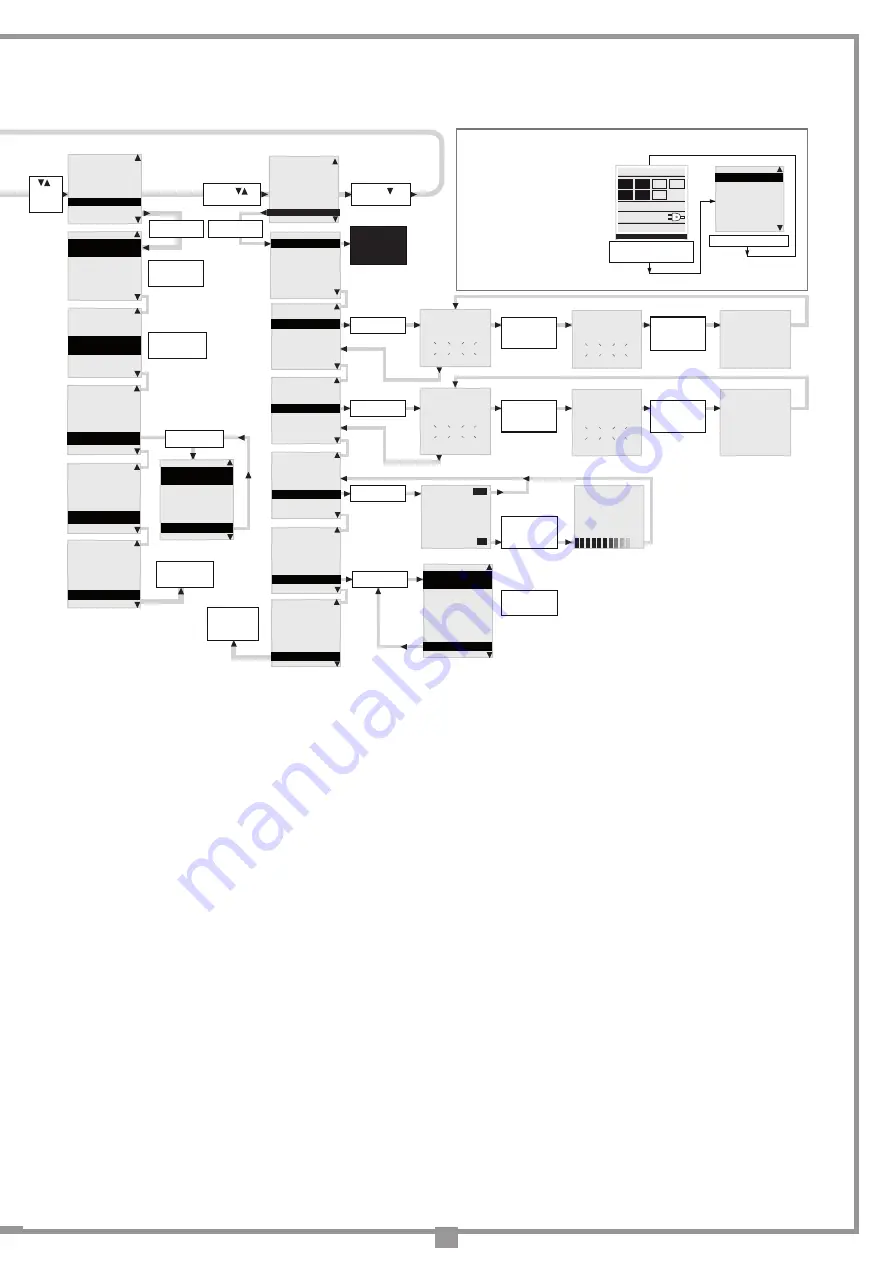
OPCIONES
SEGURIDADES
MARCHA
PANTALLA
CALENDARIO
CÓDIGOS RADIO
PROGRAM
TB FI
FS CP
TA TD
TC
00.000.007
OPCIONES
SEGURIDADES
MARCHA
PANTALLA
CALENDARIO
CÓDIGOS RADIO
Flecha
para desplazar
TECLA DINÁMICA
ABRE-CIERRA/
ABRE-STOP-CIERRA
CIERRA AUTOMATICA
ON/OFF
PRERRELAMPAGUEO
ON/OFF
OPCIONES
SEGURIDADES
MARCHA
PANTALLA
CALENDARIO
CÓDIGOS RADIO
Flecha
para desplazar
OPCIONES
SEGURIDADES
MARCHA
PANTALLA
CÓDIGOS RADIO
Flecha
para desplazar
TECLA DINÁMICA
ABRE-CIERRA/
ABRE-STOP-CIERRA
CIERRA AUTOMATICA
ON/OFF
PRERRELAMPAGUEO
ON/OFF
TECLA DINÁMICA
ABRE-CIERRA/
ABRE-STOP-CIERRA
CIERRA AUTOMATICA
ON/OFF
PRERRELAMPAGUEO
ON/OFF
CIERRA AUTOMATICA
ON/OFF
PRERRELAMPAGUEO
ON/OFF
LUZ TESTIGO
FIJA/
INTERMITENTE
LUZ TESTIGO
FIJA/
INTERMITENTE
LUCES EN BARRA
FIJA/
INTERMITENTE
FOTOCELULA INV.
EN CIERRE/
ADEMAS EN STOP
LUCES EN BARRA
FIJA/
INTERMITENTE
FOTOCELULA INV.
EN CIERRE/
ADEMAS EN STOP
TEST FI
ON/OFF
FOTOCELULA INV.
EN CIERRE/
ADEMAS EN STOP
TEST FI
ON/OFF
TEST FS
ON/OFF
TEST FS
ON/OFF
BARRA INSTALADA
IZQUIERDA
MEMO RADIO
ON/OFF
TEST FI
ON/OFF
TEST FS
ON/OFF
BARRA INSTALADA
IZQUIERDA
“PROG/OK”
para confirmar
“PROG/OK”
para cambiar
el valor
“PROG/OK”
para cambiar
el valor
“PROG/OK”
para cambiar
el valor
“PROG/OK”
para cambiar
el valor
“PROG/OK”
para cambiar
el valor
“PROG/OK”
para cambiar
el valor
“PROG/OK”
para cambiar
el valor
“PROG/OK”
para cambiar
el valor
“PROG/OK”
para cambiar
el valor
CONTACTO TB
NC/8K2
CONTACTO FI
NC/8K2
CONTACTO FS
NC/8K2
CONTACTO TB
NC/8K2
CONTACTO FI
NC/8K2
CONTACTO FS
NC/8K2
“PROG/OK”
para confirmar
“PROG/OK”
para cambiar
el valor
“PROG/OK”
para cambiar
el valor
CONTACTO TB
NC/8K2
CONTACTO FI
NC/8K2
CONTACTO FS
NC/8K2
“PROG/OK”
para cambiar
el valor
CONTACTO FI
NC/8K2
CONTACTO FS
NC/8K2
CONTACTO CP
NC/8K2
“PROG/OK”
para cambiar
el valor
CONTACTO FS
NC/8K2
CONTACTO CP
NC/8K2
SALIDA
“PROG/OK”
para regresar al
menú seguridades
“PROG/OK”
para confirmar
CONTRASTE
0....63
RETROILUMINACION
SIEMPRE ON/ 60/30 SEG.
SALIDA
“PROG/OK”
para confirmar
CONTRASTE
0....63
RETROILUMINACION
SIEMPRE ON/ 60/30 SEG.
SALIDA
“PROG/OK”
para cambiar
el valor
CONTRASTE
0....63
RETROILUMINACION
SIEMPRE ON/ 60/30 SEG.
SALIDA
“PROG/OK”
para regresar al
menú pantalla
El número de las
maniobras del
barrera, la fecha
y la hora quedan
siempre
visualizado en la
pantalla inicial
del display en
este caso.
El símbolo
indica que la
centralita está
alimentada por la
red principal.
El símbolo
indica que la
centralita está
alimentada por la
batería cargada
al 100%.
75%
50%
25%
0%
Nota: 1
Nota: 2
PRERRELAMPAGUEO
ON/OFF
LUZ TESTIGO
FIJA/
INTERMITENTE
LUCES EN BARRA
FIJA/
INTERMITENTE
“PROG/OK”
para cambiar
el valor
Nota: 1
SELECCIÓN MOTOR
ELDOM24 3/4M-6M
SENSOR CORRIENTE
NIVEL 1...5
FRENADA EN CIERRE
REGULACION 1...9
SELECCIÓN MOTOR
ELDOM24 3/4M-6M
SENSOR CORRIENTE
NIVEL 1...5
FRENADA EN CIERRE
REGULACION 1...9
“PROG/OK”
para cambiar
el valor
SENSOR CORRIENTE
NIVEL 1...5
FRENADA EN CIERRE
REGULACION 1...9
RALENTIZ. EN CIERRE
REGULACION 1...9
“PROG/OK”
para cambiar
el valor
“PROG/OK”
para cambiar
el valor
Nota: 6
Nota: 8
07-06-13 15.35
SELECCIÓN MOTOR
ELDOM24 3/4M-6M
SENSOR CORRIENTE
NIVEL 1...5
FRENADA EN CIERRE
REGULACION 1...9
“PROG/OK”
para cambiar
el valor
OPCIONES
SEGURIDADES
MARCHA
PANTALLA
CALENDARIO
CÓDIGOS RADIO
Flecha
para
desplazar
CONFIGURAR HORA
08:00
CONFIGURAR FECHA
23-12-13
CONFIGURAR EVENTOS
CONFIGURAR HORA
08:00
CONFIGURAR FECHA
23-12-13
CONFIGURAR EVENTOS
“PROG/OK”
para cambiar
el valor
CONFIGURAR HORA
08:00
CONFIGURAR FECHA
23-12-13
CONFIGURAR EVENTOS
“PROG/OK”
para confirmar
“PROG/OK”
para confirmar
EVENTO 0
LU-DO 08-10 TA 1
EVENTO 1
LU-DO 08-10 TA 1
EVENTO 2
LU-VI 10-08 TA 0
SALIDA
CONFIGURAR FECHA
23-12-13
CONFIGURAR EVENTOS
SALIDA
CONFIGURAR EVENTOS
EVENTOS: ON/OFF
SALIDA
“PROG/OK”
para confirmar
PULSAR el
canal por
memorizar en
el emisor
PULSAR el
mismo canal
por memorizar
en el emisor
“PROG/OK”
para confirmar
Flecha
para desplazar
CODIFICACIÓN: S4XX
MEMORIZACIÓN
CANCELACIÓN
CANCEL. TOTAL
FUNCIÓN CANALES
SALIDA
“PROG/OK”
para confirmar
OPCIONES
SEGURIDADES
MARCHA
PANTALLA
CALENDARIO
CÓDIGOS RADIO
MEMORIZACIÓN
[n....]
* * * * * * * * * * * * * * *
* *
* ACTIVACIÓN 1 *
* *
* * * * * * * * * * * * * * *
MEMORIZACIÓN
[n....]
* * * * * * * * * * * * * * *
* *
* ACTIVACIÓN 2 *
* *
* * * * * * * * * * * * * * *
MEMORIZACIÓN
[n....]
* * * * * * * * * * * * * * *
* *
* CÓDIGO *
* MEMORIZADO *
* * * * * * * * * * * * * * *
“PROG/OK”
para confirmar
CANCELACIÓN
[n....]
* * * * * * * * * * * * * * *
* *
* ACTIVACIÓN 1 *
* *
* * * * * * * * * * * * * * *
PULSAR el
canal por
cancelar en
el emisor
CANCELACIÓN
[n....]
* * * * * * * * * * * * * * *
* *
* ACTIVACIÓN 2 *
* *
* * * * * * * * * * * * * * *
PULSAR el
canal por
cancelar en
el emisor
CANCELACIÓN
[n....]
* * * * * * * * * * * * * * *
* *
* CÓDIGO *
* CANCELADO *
* * * * * * * * * * * * * * *
CODIFICACIÓN: S4XX
MEMORIZACIÓN
CANCELACIÓN
CANCEL. TOTAL
FUNCIÓN CANALES
SALIDA
“PROG/OK”
para confirmar
* * * * * * * * * * * * * * *
* CANCELAR *
* LA MEMORIA ? *
* * * * * * * * * * * * * * *
PULSAR ok para
cancelar la
memoria o
exit para salir
CODIFICACIÓN: S4XX
MEMORIZACIÓN
CANCELACIÓN
CANCEL. TOTAL
FUNCIÓN CANALES
SALIDA
Flecha
para salir
EXIT
OK
* * * * * * * * * * * * * * *
* CANCELACIÓN *
* EN CURSO *
* * * * * * * * * * * * * * *
CODIFICACIÓN: S4XX
MEMORIZACIÓN
CANCELACIÓN
CANCEL. TOTAL
FUNCIÓN CANALES
SALIDA
CANAL A
función canal A
CANAL B
función canal B
CANAL C
función canal C
CANAL D
función canal D
SALIDA
CODIFICACIÓN: S4XX
MEMORIZACIÓN
CANCELACIÓN
CANCEL. TOTAL
FUNCIÓN CANALES
SALIDA
“PROG/OK”
para cambiar
el valor
“PROG/OK”
para regresar al
menú calendario
CODIFICACIÓN: S4XX
MEMORIZACIÓN
CANCELACIÓN
CANCEL. TOTAL
FUNCIÓN CANALES
SALIDA
“PROG/OK”
para cambiar
el valor
S4XX a S500
“PROG/OK”
para regresar
al menú
códigos radio
[AB--]
[AB--]
[AB--]
[AB--]
[AB--]
[AB--]
Nota: 11
ITALIANO
FRANÇAIS
ENGLISH
NEDERLANDS
DEUTSCH
ESPAÑOL
PROGRAM
TB FI
FS
CP
TA TD
TC
00.000.007
07-06-13 15.35
para entrar en el submenú
idioma pulsar simultáneamente
ambas flechas
“PROG/OK” para confirmar
• Pulsar las teclas derecha e
izquierda simultáneamente
para entrar en el submenú.
• Pulsar la tecla derecha o
izquierda para cambiar el
idioma: italiano - español.
• Pulsar la tecla "PROG/OK"
para confirmar el idioma:
Selección del idioma
:
Nota: 13
Nota: 12
RESET PARAMETROS
OK.
VERSIÓN FW
ELDOM24 V0.04
SALIDA
“PROG/OK”
para regresar al
menú marcha
FRENADA EN CIERRE
REGULACION 1...9
RALENTIZ. EN CIERRE
REGULACION 1...9
RALENTIZ. APERTURA
REGULACION 1...9
“PROG/OK”
para cambiar
el valor
DISTANCIA TOPE DE
APERTURA 1...9 PASOS
VELOCIDAD DE CIERRE
LIVELLO 1...3
TIEMPO DE PAUSA
130 SEG.
VELOCIDAD DE CIERRE
LIVELLO 1...3
TIEMPO DE PAUSA
130 SEG.
RESET PARAMETROS
OK.
“PROG/OK”
para confirmar
* * * * * * * * * * * * * * *
* *
*
TIEMPO DE PAUSA
*
*
SEG.
*
* *
* * * * * * * * * * * * * * *
180
“PROG/OK”
para confirmar
Pulsar las flechas
para incrementar o
reducir el valor
(240 segundos máx.).
Manteniendo pulsada
la flecha por más
tiempo, el valor
cambia rápidamente.
RALENTIZ. EN CIERRE
REGULACION 1...9
RALENTIZ. APERTURA
REGULACION 1...9
DISTANCIA DESDE EL
TOPE DE CIERRE
1...9 PASOS
RALENTIZ. APERTURA
REGULACION 1...9
DISTANCIA TOPE DE
CIERRE 1...9 PASOS
DISTANCIA DESDE EL
TOPE DE APERTURA
1...9 PASOS
DISTANCIA TOPE DE
CIERRE 1...9 PASOS
DISTANCIA TOPE DE
APERTURA 1...9 PASOS
VELOCIDAD DE CIERRE
LIVELLO 1...3
TIEMPO DE PAUSA
130 SEG.
RESET PARAMETROS
OK.
VERSIÓN FW
ELDOM24 V0.04
Nota: 9
Nota: 10
BARRA INSTALADA
IZQUIERDA
MEMO RADIO
ON/OFF
ERR 230V BARRA ^
ON/OFF
MEMORADIO
ON/OFF
ERR 230V BARRA ^
ON/OFF
CIERRE RÁPIDO
ON/OFF
“PROG/OK”
para cambiar
el valor
“PROG/OK”
para cambiar
el valor
Nota: 4
Nota: 3
“PROG/OK”
para regresar al
menú opciones
ERR 230V BARRA ^
ON/OFF
CIERRE RÁPIDO
ON/OFF
AUX1 - AUX2
CH2/LUZ DE ZONA
CIERRE RÁPIDO
ON/OFF
AUX1 - AUX2
CH2/LUZ DE ZONA
SALIDA
“PROG/OK”
para cambiar
el valor
Nota: 5
Nota: 7
• Es necesario configurar los parámetros de funcionamiento fundamentales (p. ej.: instalación derecha/izquierda) en el menú memorizaciones.
• Si hay seguridades con contacto 8.2 kΩ, cambiar la configuración en el menú seguridades.
• Antes de efectuar la programación de la carrera de la barra, configurar el motor correcto en la posición "selección motor" del menú "MARCHA".
12) Funciones de los canales
Cada canal del radiomando
"
A
","
B
","
C
","
D
" puede
configurarse seleccionando
e n t r e 6 f u n c i o n e s
disponibles:
-
TD
tecla dinámica
-
TA
apertura
-
TC
cierre
- Bloqueo
-
CH2
salida segundo canal
de radio
- eventos On/Off
5) Aux1 - Aux2:
- cerrado / abierto -
aux 1
= señal barrera cerrada -
aux 2
= señal barrera abierta;
- ch2 / luz de cortesía -
aux 1
= habilita el segundo canal de la radio -
aux 2
= contacto para la luz de cortesía;
- cerrado / luz de cortesía -
aux 1
= señal barrera cerrada -
aux 2
= luz de cortesía.
6) Configuración del sensor de corriente:
-
Nivel 1
= absorción del motor +
2
amperios
-
Nivel 2
= absorción del motor +
3
amperios
-
Nivel 3
= absorción del motor +
4
amperios
-
Nivel 4
= absorción del motor +
5
amperios
-
Nivel 5
= absorción del motor +
6
amperios
Cuando el sensor interviene, la barra invierte inmediatamente el movimiento por unos
10 cm
, tanto en cierre como en apertura, para liberar el obs-
táculo; después queda inmóvil durante
3 minutos
y, transcurrido este lapso de tiempo, reanuda el movimiento en la dirección en la que se había
interrumpido, después de haber efectuado un parpadeo previo de unos
10 segundos
.
7) Frenada en cierre:
Durante el cierre, cuando todavía faltan algunos grados para completar la maniobra, interviene una fuerte ralentización que acompaña dulcemente la
barra hasta el final. El parámetro regula la distancia desde el tope de cierre en el que interviene esta ralentización. El valor "
9
" significa que la ralenti-
zación final empezará mucho antes del tope de cierre. Por lo general, el valor por defecto "
2
" configurado en fábrica satisface casi todos los casos.
8) Ralentización en cierre / apertura:
Estos dos parámetros regulan el punto de partida de la desaceleración del barra. Un número más alto significa más espacio de ralentización, un
número más bajo significa menos espacio de ralentización. Antes de proceder, comprobar el equilibrado del muelle ya que los valores por defecto
están calibrados para un movimiento ideal
9) Configuración de la distancia desde el tope de cierre/apertura:
Para incrementar o disminuir esta distancia, modificar el parámetro de
0
a
9
. "
0
" = significa que la barra se detendrá más cerca del tope, "
9
" significa
que la barra se detendrá más lejos del tope.
10) Velocidad de cierre:
El parámetro regula la velocidad de cierre global "
1
" = velocidad máxima "
2
" = velocidad media "
3
" = velocidad mínima.
11) Eventos On/Off:
Al configurar uno de los canales radio con función eventos on/off, es posible activar/desactivar los eventos mediante mando radio. La activación será
señalada con un destello de 6 segundos de la luz parpadeante y la luz piloto. La desactivación será señalada con un destello de 3 segundos
11) Codificación:
Antes de cambiar
el tipo de codificación es necesario cambiar el módulo de memoria de
S4XX
a
S500
y viceversa con la central no alimentada.


