background image

6

5. Operating Standards

The units described in this manual are classified for use as stationary equipment in a Pollution Degree 2 and 

Over voltage Category II environment.
These units are designed to operate under the following environmental conditions:

•  Indoor use
•  Altitude up to 2000 m (6512 feet)
•  Maximum relative humidity 60% for temperatures from 15°C to 32°C (59°F to 90°F)
•  Main supply voltage fluctuations not to drop or exceed by 10% of the nominal voltage
•  Do not connect the unit to a GFCI (Ground Fault Circuit Interrupter) protected outlet as it may be subject to 

nuisance tripping

•  Do not run this unit off the extension cords

Unit Specifications

The data label is located on the left side on top towards front of the unit.
The specifications of refrigerator like voltage, required wall breaker amperage and power plug are same for all 

the units.
Voltage = 115V / 60Hz
Amps - Refer to data label for unit rating. The power supply cord plug indicates the WLL circuit breaker rating 

at 15A.
Chromatography Power Plug = NEMA 5-15P
General Purpose Refrigerator Power Plug = NEMA 5-15P
This plug must be plugged into/supplied with it's own individual branch circuit.

CAUTION:

 Chromatography units are supplied with two separate power cords. Be careful to unplug 

both during movement, testing or repair of the product.

Other specifications are listed in the table below.

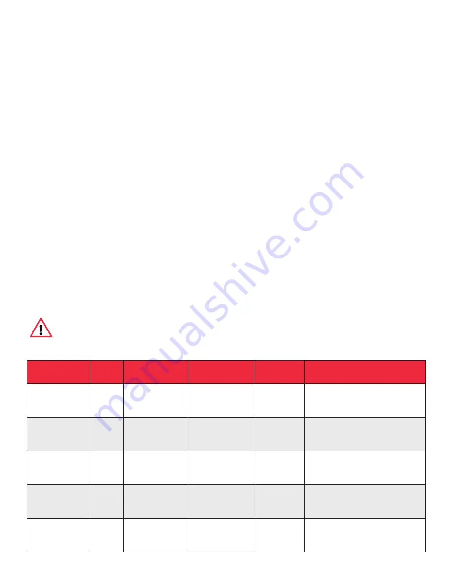
UNIT

SIZE

(Cu.ft.)

EXTERIOR

DOOR TYPE

NO.OF

SHELVES

EXTERIOR DIMENSIONS

(H x W x D)

CHG12RPGA

12

Painted

Glass

4

1925.9 x 628.6 x 635.0 mm
(75.82 x 24.75 x 25.00 in)

CHG25RPGA

25

Painted

Glass

4

2057.1 x 704.8 x 812.8 mm
(81.00 x 27.75 x 32.00 in)

CHG25RPSA

25

Painted

Solid

4

2057.1 x 704.8 x 812.8 mm
(81.00 x 27.75 x 32.00 in)

CHG25RSGA

25

Stainless Steel

Glass

4

2057.1 x 704.8 x 812.8 mm
(81.00 x 27.75 x 32.00 in)

CHG25RSSA

25

Stainless Steel

Solid

4

2057.1 x 704.8 x 812.8 mm
(81.00 x 27.75 x 32.00 in)

Summary of Contents for CHG12RPGA

Page 1: ...and Operation CHG12RPGA CHG25RPGA CHG25RPSA CHG25RSGA CHG25RSSA CHG30RPGA CHG30CPGA CHG30RPSA CHG30RSGA CHG30CSGA CHG30RSSA CHG45RPLA CHG45CPLA CHG45RSLA CHG45CSLA CHG49RPGA CHG49CPGA CHG49RPSA CHG49RSGA CHG49CSGA CHG49RSSA CHG72RPGA CHG72CPGA CHG72RSGA CHG72CSGA ...

Page 2: ...d maintenance must be performed by qualified service personnel Material in this manual is for informational purposes only The contents and the product it describes are subject to change without notice Cardinal Health makes no representations or warranties with respect to this manual In no event shall Cardinal Health be held liable for any damages direct or incidental arising from or related to the...

Page 3: ...18 7 Startup 19 Initial Startup 19 Chromatography Refrigerators 19 Product Loading and Unloading Guidelines 19 8 Operation 20 Control Panel 20 Temperature Setpoint 21 Alarms 21 Password Protection 23 Controller Parameter Settings 23 9 Maintenance 27 Cleaning the Cabinet Interior 27 Cleaning the Unit Chromatography Refrigerators 27 Cleaning the Condenser 27 Automatic Defrost 27 Gasket Maintenance 2...

Page 4: ...3 Regulatory Compliance 34 Product Safety 34 Hydrocarbon Refrigerants 34 Electromagnetic Compatibility 34 Canadian ISED IC Notice 34 Energy Efficiency 34 Additional Regulations and Markings 34 14 Contact Information 35 ...

Page 5: ...A CHG49RPSA CHG30RPGA CHG49RSGA CHG30CPGA CHG49CSGA CHG30RPSA CHG49RSSA CHG30RSGA CHG72RPGA CHG30CSGA CHG72CPGA CHG30RSSA CHG72RSGA CHG45RPLA CHG72CSGA CHG45CPLA The annotation of model numbers is given in the following table SERIES CHG Cardinal Health Size cu ft 12 25 30 45 49 72 Type R Refrigerator C Chromatography Exterior P Painted S Stainless Door Type S Solid G Glass L Sliding glass Voltage ...

Page 6: ... cause the product to malfunction which could result in injury or damage CAUTION This symbol indicates possible pinch points which may cause personal injury WARNING The snowflake symbol indicates low temperatures and risk of frost bite Do not touch bare metal or samples with unprotected body parts Below are important safety precautions that apply to this product CAUTION Use this product only as de...

Page 7: ...y to chromatography refrigerator models CAUTION Equipment should only be powered using the internal outlet In case of a leak the safety circuit will remove power to the outlet in the unit but shall have no control over equipment power via battery or externally Do not use instrumentation or equipment that incorporates potential ignition sources e g open contact switching brushed DC and AC motors et...

Page 8: ...the manufacturer without written authorization When submitting a claim for shipping damage request that the carrier inspect the shipping container and equipment Packing List Along with the unit following things will be packed Installation and Operation manual is placed in the white envelope Door Lock Key and Power Key Switch is wire tied to the pilaster on the upper top front Small bag with shelvi...

Page 9: ...ic use or for samples to be re introduced to the body This unit is not intended for use in classified hazardous locations nor to be used for the storage of flammable or corrosive inventory These refrigerators are not suitable for outdoor location CAUTION Storage of unsealed corrosive substances may cause the interior of the unit to corrode Initial Loading Allow the unit to operate at the desired t...

Page 10: ...re same for all the units Voltage 115V 60Hz Amps Refer to data label for unit rating The power supply cord plug indicates the WLL circuit breaker rating at 15A Chromatography Power Plug NEMA 5 15P General Purpose Refrigerator Power Plug NEMA 5 15P This plug must be plugged into supplied with it s own individual branch circuit CAUTION Chromatography units are supplied with two separate power cords ...

Page 11: ...1 x 781 0 x 812 8 mm 81 00 x 30 75 x 32 00 in CHG45RPLA 45 Painted Sliding Glass 8 2057 1 x 1338 6 x 812 8 mm 81 0 x 52 7 x 32 0 in CHG45CPLA 45 Painted Sliding Glass 8 2 Half Shelves 2057 1 x 1338 6 x 812 8 mm 81 0 x 52 7 x 32 0 in CHG45RSLA 45 Stainless Steel Sliding Glass 8 2057 1 x 1338 6 x 812 8 mm 81 0 x 52 7 x 32 0 in CHG45CSLA 45 Stainless Steel Sliding Glass 8 2 Half Shelves 2057 1 x 1338...

Page 12: ...057 1 x 1338 6 x 812 8 mm 81 0 x 52 7 x 32 0 in CHG72RPGA 72 Painted Glass 12 2057 1 x 1924 0 x 812 8 mm 81 00 x 75 75 x 32 00 in CHG72CPGA 72 Painted Glass 12 2 Half Shelves 2057 1 x 1924 0 x 812 8 mm 81 00 x 75 75 x 32 00 in CHG72RSGA 72 Stainless Steel Glass 12 2057 1 x 1924 0 x 812 8 mm 81 00 x 75 75 x 32 00 in CHG72CSGA 72 Stainless Steel Glass 12 2 Half Shelves 2057 1 x 1924 0 x 812 8 mm 81 ...

Page 13: ...ately 1 2 4 Pull grill away from the refrigerator Pallet Removal and Caster Installation Instructions Note Casters available for all refrigerators 12 25 30 45 49 and 72 cu ft and 25 34 49 cu ft freezers leveling feet only on 20 cu ft refrigerator freezer units CAUTION Avoid damage to the refrigerant tubing which may cause a refrigerant leak while handling moving and operating this unit Note It is ...

Page 14: ...nt grill after placing the refrigerator in the desired location and tighten the screws with a screwdriver 3 Remove bolts 4 holding the unit to the pallet using the 7 16 wrench Note From this step onward a minimum of 2 people are required Use additional people if necessary Note It is recommended to use a forklift for double and triple door units refer to installation with Forklift instructions 4 Wi...

Page 15: ... a Install the casters with 8 sets of 5 16 18x1 hex head bolts 5 16 nuts and 7 8 O D washer supplied with the package b Re use the 8 sets of 5 16 18x1 hex head bolts 5 16 nuts and 7 8 O D washer to install the 2 casters without lock in the rear of the cabinet 6 While supporting the unit carefully slide the unit until the casters reach the ground Gently slide the back edge off of the pallet approxi...

Page 16: ... 2 people Required Tools for Double and Triple Door Unit 45 49 72 cu ft Models Phillips head screwdriver 7 16 5 16 18 wrenches and a minimum of 2 people All the units are shipped with factory installed feet with rolling casters supplied inside of the unit The following instructions demonstrate how to remove the cabinet from its shipping base pallet and install the casters without use of a forklift...

Page 17: ...he internal outlet will be discontinued The user will need to manually reset the safety circuit assembly using the reset switch at the right side of header panel before the power is restored To do this toggle the switch located on the top right side of the header panel beside the remote alarm contacts There will be a power delay to the outlet for approximately 4 minutes where the red LED will be i...

Page 18: ...r personal safety and trouble free operation this unit must be properly grounded while in use Failure to ground the equipment may cause personal injury or damage to the equipment Always conform to the National Electrical Code and local codes Do not connect the unit to overloaded power lines CAUTION Always connect the unit to a dedicated separate circuit Each unit is equipped with a service cord an...

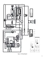
Page 19: ...ONTROLLER DETAIL SEE CONTROLLER DETAIL 2 J4 J2 J3 1 2 ROCKER SWITCH 1 J6 5 3 4 2 1 AC OUTLET RELAY 1 2 DC IN 1 J5 2 4 3 2 1 HC SENSOR BOARD 3 1 2 4 1 2 4 3 5 6 8 7 GREEN LED RED LED POWER SUPPLY SIGNAL CONDITIONING BOARD KEY SW 45 90 7 8 5 1 NC COM COIL RELAY FORM C KEY SW 90 6V BATTERY BUZZER LED 4 5 4 3 8 7 1 BLACK BLUE YELLOW BLACK BLACK BLACK RED BROWN BLACK BROWN WHITE BLUE BLUE BROWN BLUE BR...

Page 20: ...sired locations Figure 2 Shelf Arrangement Figure 3 Shelf Clip Installation Instructions WARNING Do not move this unit while it is loaded 1 Determine appropriate location for shelves clips the reference number on the pilaster can serve as a guide to ensure all clips are properly located 2 Insert top of the clip into the desired hole of the pilaster Ensure that the retaining tab should be facing up...

Page 21: ...e factory installed remote alarm contacts that can be used for remote alarm systems The maximum distance between a unit and a remote alarm depends on the wire gauge used The Remote alarm contacts are located on the right side of the header panel The three terminals are COMMON OPEN ON FAIL Normally Closed and CLOSE ON FAIL Normally Open Wire Gauge Total Wire Length feet Distance to Alarm 1 2 Wire L...

Page 22: ...re start up be sure to complete the following steps 1 Make sure that the unit is free of all wood or cardboard shipping materials both inside and outside 2 Ensure that the shelves are positioned in the desired location 3 Verify that the unit is connected to a dedicated circuit ...

Page 23: ...rature Note The Chromatography refrigerator is shipped with the manual reset switch on the right side of the header panel above the remote alarm contacts refer to section Switches as ON The Manual reset switch should always be in ON position 5 The red LED on the chromatography safety circuit turns ON 6 After a power delay of 4 minutes the red LED on the chromatography safety circuit turns Off and ...

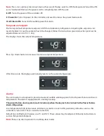
Page 24: ...m Present Flashing Alarm Silenced Off No Alarm On Fixed Compressor Active Flashing Delay Protection or Activation Blocked Off No Alarm 2 Defrost This button is used to go back from the parameter settings 3 SC This button is used to turn the cabinet LED light on and off with a single touch This button is also used for selecting an option in parameters 4 Up Scrolls the menu items and increases the v...

Page 25: ...o 5 5 C only The display shows the current temperature Press Up Down button to increase decrease setpoint temperature After 30 seconds the display automatically reverts to the current temperature Alarms The alarm system is designed to provide visual and audible warning signals for both power failure and rise in temperature The alarm is equipped with a battery backup The power failure alarm system ...

Page 26: ... more than ALA dod Always Blink dor If configured cut in alarm relay beep the buzzer Door open alarm E01 S1 error Always Blink E01 If configured cut in alarm relay beep the buzzer S1 sensor failure short or open E02 S2 error Always Blink E02 If configured cut in alarm relay beep the buzzer S2 sensor failure short or open Alarm Silencing To mute the power fail alarm change the key switch to Power O...

Page 27: ...button to confirm 4 Scroll to PS1 parameter and Press SC button to confirm 5 Scroll Up Down buttons to enter the desired password 6 Press SC button to confirm After 30 seconds the display automatically reverts to showing the current temperature If this does not happen press the Defrost button twice Controller Parameter Settings To access the controller settings you must enter the password and the ...

Page 28: ...n 0 min 0 min fdd Fan Delay After Defrost 0 sec 0 sec 0 sec ftd Fan Start Temp 10 C 10 C 10 C dFa Defrost Fan On Yes Yes Yes dCt Defrost On Compressor Time No No No doC Defrost by Comp Running Time 1 hour 1 hour 1 hour dEt Defrost Start Evaporator Temp 0 C 0 C 0 C ddt Defrost Delta T 3 0 k 3 0 k 3 0 k idi Initial Defrost Interval 0 hour 0 hour 0 hour idd Initial Defrost Duration 0 cycle 0 cycle 0 ...

Page 29: ...in Cdd Compressor Door Open Delay 0 min 0 min 0 min Srt System Resume After Door Open 0 min 0 min 0 min Pod Power On Delay 60 sec 60 sec 60 sec Pot Power ON Temperature 16 C 16 C 16 C diS Display Settings diC Display Intensity Auto Control No No No din Display Intensity 8 8 8 CFu Display Unit C C C trS Temp Sensor to Display Sco Sco Sco rES Display Resolution 1 1 1 rLT Display Range Limit No No No...

Page 30: ...mbol No No No SdS Show Defrost Symbol No No No SES Show ECO Symbol No No No idP Info Menu Display Item 15 15 15 SSC Show Pull Down No No No ALA Alarm Settings HAt High Temp Alarm 10 C 10 C 10 C LAt Low Temp Alarm 2 C 2 C 2 C Htd High Alarm Delay 0 min 0 min 0 min Ltd Low Alarm Delay 0 min 0 min 0 min dod Door Open Delay 1 min 1 min 1 min ACA Auto Clearance of Alarm Yes Yes Yes Note 45 cu ft slidin...

Page 31: ...an result in equipment warm up or erratic temperatures CAUTION Never clean around the condensers with your fingers Some surfaces are sharp The condenser is located at the bottom in front of the unit To clean the condenser complete the following steps 1 Disconnect the power 2 Vacuum the condenser and clean up any loose dust 3 Reconnect power Automatic Defrost The defrosting process on all the model...

Page 32: ...4 AA Alkaline 1 5 V batteries The back up time for the alarm battery system is 60 hours Battery must be replaced after an active alarm or after every 12 months whichever is the earliest Steps to follow for battery replacement 1 Locate the knurled thumb screw on the left side of the header panel 2 Remove the knurled thumb screw by hand 3 Once the screws are removed wear hand gloves and gently pull ...

Page 33: ...erature goes below freezing in the cabinet Use system alarms to ensure the temperature inside the unit is always above 0 C The sensors must be replaced if exposed to freezing conditions If the display shows an error and sounds an alarm in case of a control defrost bottle or ambient probe failure the sensor needs to be replaced Sensor Maintenance Chromatography Refrigerators The sensor should be re...

Page 34: ...uild up on refrigeration coils Turn unit off and allow it to defrost Remove contents from top shelf of unit Unit runs continuously Dirty condenser Clean condenser Space temperature too high Control setting too high Reset control Inadequate air circulation Improve air movement Temperature fluctuates insufficient cooling Temperature control Make sure that the control is set correctly Condenser clogg...

Page 35: ... Make sure the door is completely closed Warm product recently loaded in unit Check the door seal Power supply Allow ample time to recover from loading warm product Compressor not functioning If the compressor is not running and the power audible is on have an electrician check for proper voltage to the unit If the compressor is not running and the power failure alarm is off call the customer serv...

Page 36: ...ow 1 Remove items and defrost unit Be sure to clean up any biological safety hazards 2 Remove the cabinet door to help prevent entrapment inside of a unit 3 Have a certified technician remove the refrigerant and compressor then drain the compressor and oil from the system Dispose of components following local regulations ...

Page 37: ...ng of the products v use of the products in combination with equipment or software not supplied by Cardinal Health or vi installation maintenance repair service relocation or alteration of the products by any person other than Cardinal Health or its authorized representative To obtain proper warranty service you must contact the nearest authorized service center or Dealer Cardinal Health Inc s own...

Page 38: ...t 15 of the FCC Rules These limits are designed to provide reasonable protection against harmful interference when the equipment is operated in a commercial environment This equipment generates uses and can radiate radio frequency energy and if not installed and used in accordance with the instruction manual may cause harmful interference to radio communications Operation of this equipment in a re...

Page 39: ...lth products are backed by a global technical support team ready to support your applications We offer cold storage accessories including remote alarms temperature recorders and validation services Country Sales North America 1 866 984 3766 ...

Page 40: ... IL 60085 USA 329137H03 G 2020 08 cardinalhealth com 2020 Cardinal Health All Rights Reserved CARDINAL HEALTH and the Cardinal Health LOGO are trademarks of Cardinal Health and may be registered in the US and or in other countries Patent cardinalhealth com patents ...

Reviews: