8527-0544-2M Rev B
APS Enterprise Scale
2
INSTALLATION
Unpacking (APS10, APS160, APS15 and APS30)
Remove the scale from the shipping carton. Remove all packing material and then examine
the scale to make certain there is no shipping damage. Should damage be discovered contact
the shipping company as soon as possible. The packing material and shipping carton should
be retained for possible examination by the shipping company.
Determine where the scale is to be located. It should be a smooth surface capable of
supporting both the scale and any load to be placed on the scale. It should not be in direct
sunlight nor should it be subject to air flow from heating/cooling vents, fans or similar devices.
Plug-in the 12VDC adapter to use scale. Refer to Electrical Power section of this manual for
more instruction. The scale is now ready for use.
Unpacking and Setup (APS70 and APS150)
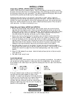
1. Remove the scale display, hardware pack, power supply, scale cover and scale base
assembly from the shipping carton. Remove all packing material and then examine the
scale to make certain there is no shipping damage. Should damage be discovered contact
the shipping company as soon as possible. The packing material and shipping carton
should be retained for possible examination by the shipping company.
2. Remove the four leveling feet from the hardware pack and install in each corner of the
bottom of the scale base. NOTE: Leveling feet must be in place to operate the scale.
3. To mount the display on the scale base, use the two included mounting screws in the
hardware pack. Insert the screws through the two holes in the scale display bracket and
attach the bracket to the scale base. Route the cable into the scale and plug into scale
display port (see interconnection section for port location and more information).
4. Determine where the scale is to be located. It should be a smooth surface capable of
supporting both the scale and any load to be placed on the scale. It should not be in direct
sunlight nor should it be subject to air flow from heating/cooling vents, fans or similar
devices.
5. Plug-in 12VDC adapter to use scale. Refer to Electrical Power section of this manual for
more instruction.
6. The scale is now ready for use.
Level Adjustment
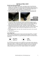
Place the scale in the chosen location and remove the stainless steel platform. The platform
can be removed by lifting upward on it removing it from the weighbridge. Locate the small
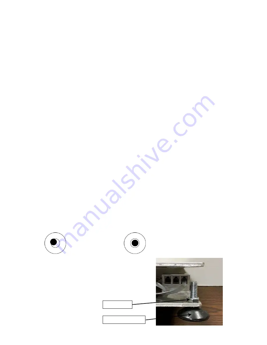
level indicator on the scale base to the right of the display and check to make certain that the
scale is level.
NOT
LEVEL
LEVEL
Bubble
is
not
Bubble
is
within
circle
within
circle
If the level indicator does not show a level indication, the
mounting feet should be adjusted to obtain a level
condition. To adjust a mounting foot, first loosen the lock
nut then turn the mounting foot in the required direction to
raise or lower that corner of the scale. Once a level
condition has been achieved, secure the mounting foot
settings by tightening each of the lock nuts. Replace the
platform on the weighbridge.
MOUNTING FOOT
LOCK NUT

