8527-0544-2M Rev G
APS Enterprise Scale
7
INSTALLATION, CONT.
Interconnections
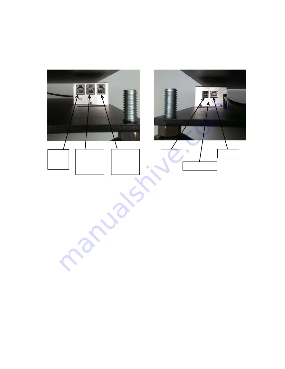
All input, output and power connections to the APS Enterprise scale are made internally to the
main board inside the scale. Connections for the scale display, remote display and OPOS
compatible serial device are made using RJ11 snap-in modular connectors. The USB port is a
device (or upstream) port using an industry standard Type B connector. The 12VDC 1A wall
plug-in UL/CSA listed AC power adapter is connected using a power jack.
Data Cable Installation
SCALE DISPLAY/SERIAL PORT 1
Plug the RJ11 connector from the Scale Display cable into the scale base as marked.
REMOTE DISPLAY/SERIAL PORT 2
To use a remote display, plug the remote display RJ11 connector into the scale base where
marked.
POS/SERIAL PORT 3
NOTE:
The included serial data cable uses an RJ11 phone type connector (scale base) to
a DB9 connector (OPOS compatible serial device).
Plug the RJ11 connector of the included 4’ serial data cable into the scale base where marked
and then plug the other end into an available serial port on the POS device.
USB Cable Installation
USB
To use the USB interface, obtain an industry standard Type B connector USB cable and plug
it into the scale base where marked and then plug the other end into a USB port on your
computer.
Power Adapter
12VDC
To apply power to the scale using the supplied 12VDC 1A wall plug-in UL/CSA listed AC
power adapter, insert the plug from the power adapter cable into the power jack on the scale
base where marked (refer to previous page) and then plug the power adapter into a proper
electrical outlet. The scale is now ready for operation.
POS
SERIAL
PORT 3
REMOTE
DISPLAY
SERIAL
PORT 2
SCALE
DISPLAY
SERIAL
PORT 1
12VDC
USB
PCB COVER


