R
L
706
110
109
BX
90
16
Step 6
࣑
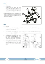
ATTENTION:
Do NOT force the pedals into their
sockets, if they do not screw in easily you
may be trying to fit the wrong pedal or
you are rotating the pedal in the wrong
direction.
Thread the pedals onto the crank arms. The
pedals are marked with R and L at the screw.
Tighten the left pedal anti-clockwise and the
right pedal clockwise.
Step 7
L
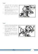
NOTICE:
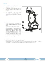
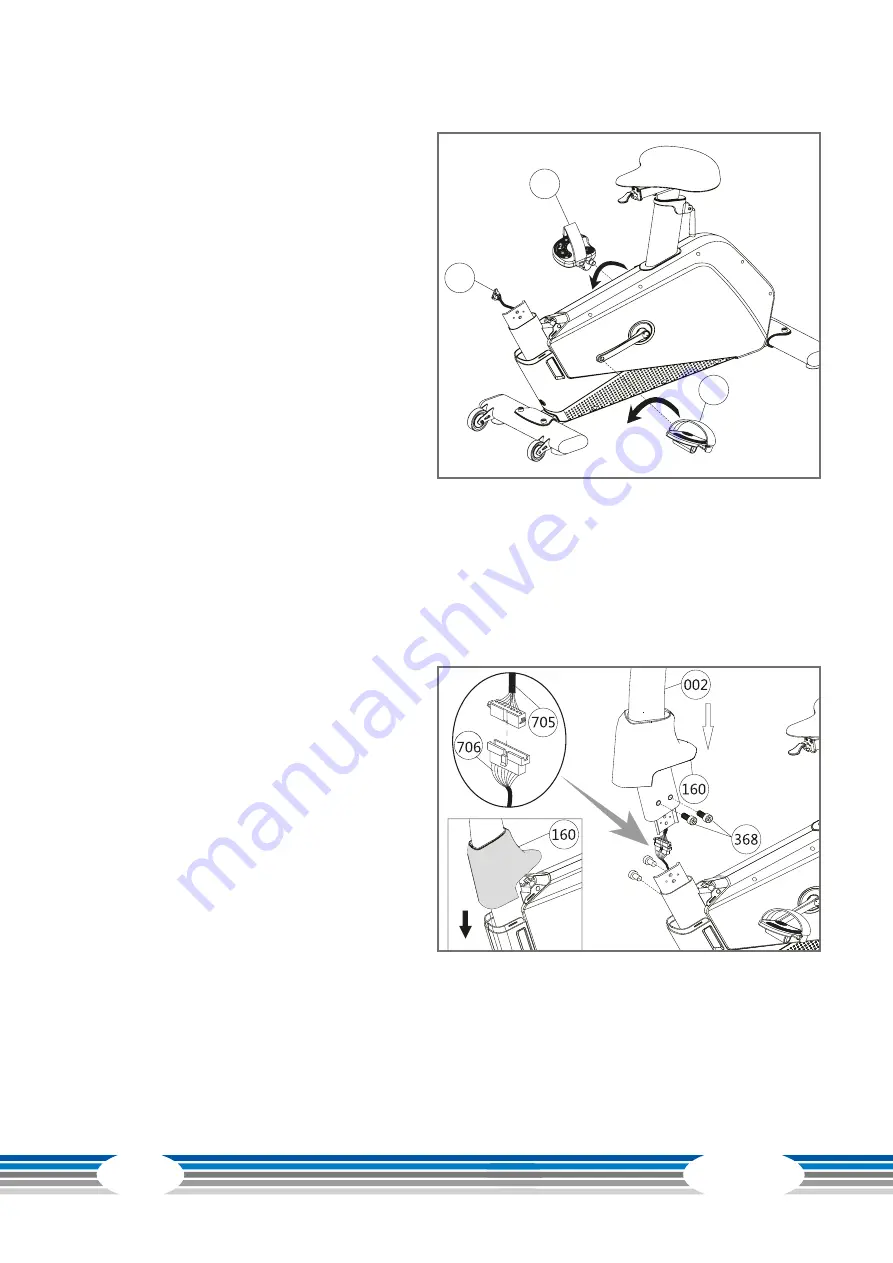
Make sure the HAT COVER [160] has already been slid into the HANDLE BAR POST [002] before
going to the following steps.
1. Hold the HANDLE BAR POST [002] in the correct position over the MAIN FRAME [001] and join
the RESISTANCE COMPUTER - CABLE
[705] & COMPUTER CABLE [706].
2. Carefully slide the HANDLE BAR POST
[002] into the MAIN FRAME [001] . Take
care not to damage the COMPUTER -
CABLE[705] & COMPUTER - CABLE [706].
3. Lift the HAT COVER [160] out of the way
and align the holes and fit 4 x BOLT [368]
then firmly tighten 4 x BOLT [368]. Slide
down the HAT COVER [160] and push
firmly.
Summary of Contents for Ergometer BX90
Page 1: ...CSTBX90 01 04 Ergometer BX90 Assembly and Operating Instructions Art No CST BX90...
Page 2: ...BX90 2...
Page 41: ...41 8 3 Exploded Drawing...
Page 46: ...BX90 46 Notes...
Page 47: ...47...
Page 48: ...Ergometer BX90...

