background image

3. Grounding

 - Take precautions so that the grounding 

or polarization means of the unit are not defeated.

4. Ventilation

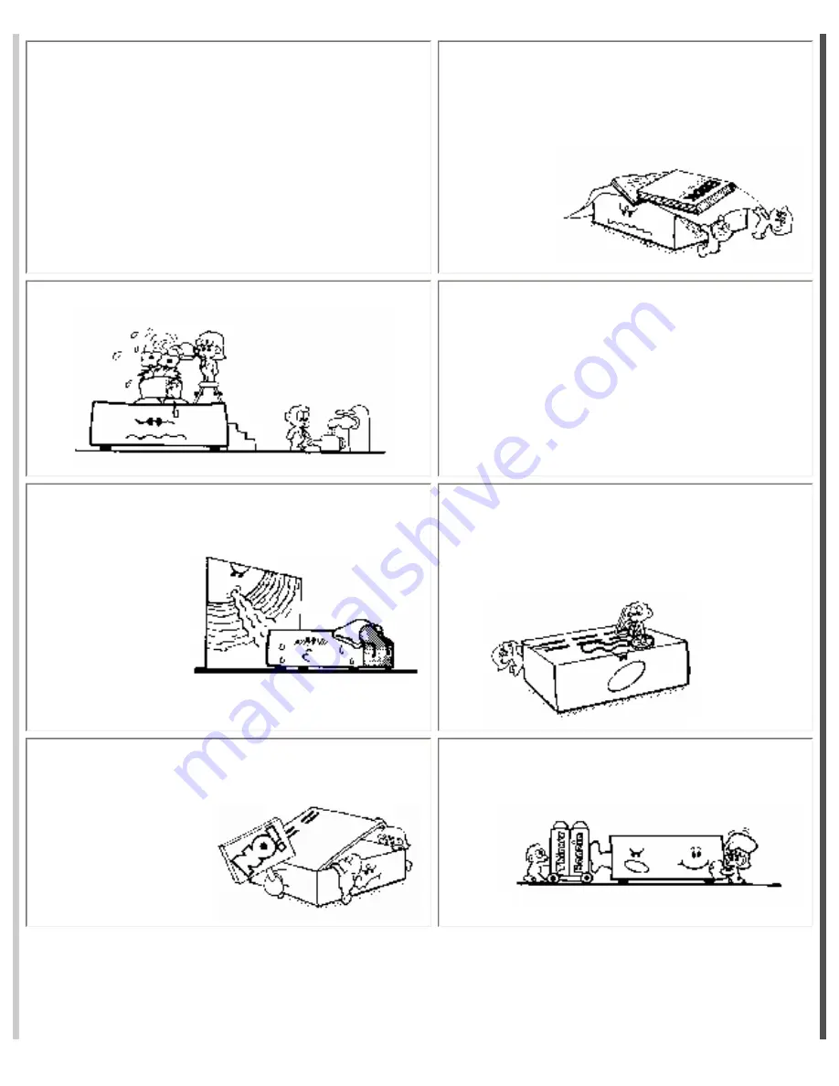
 - Position the unit so that its location 

does not interfere with ventilation. To maintain good 
ventilation, do not put items on or over the unit. Do 
not use the unit on a cushioned surface that may 
block the ventilation openings.

5. Water and moisture

 - Do not locate the unit near 

water.

6. Temperature

 - The unit may not function 

properly if used at extreme temperatures. The ideal 
temperature is 41

o

F (5

o

C) to 87

o

F (30

o

C)

7. Heat - 

The unit should be located away from heat 

sources such as radiators, heat registers, stoves, etc.

8. Electric shock

 - Care should be taken so that 

objects do not fall and liquid is not spilled on the 
enclosure. If a metal object, such as a hairpin or a 
needle, comes in contact with the inside of this unit, 
a dangerous electric shock may 
result.

9. Enclosure removal

 - Never open the enclosure. If 

the internal parts are accidentally touched, a serious 
shock may occur.

10. Cleaning

 - Do not use solvents such as alcohol; 

paint thinner, etc. to clean the unit. Use a clean dry 
cloth.

Summary of Contents for CTI SYSTEM 1600

Page 1: ...rding your installation that are not covered by this Manual or by our Troubleshooting Guide please contact our Service Department Cardio Theater Inc Service Department Telephone 1 800 776 6695 E mail service cardiotheater com Table of Contents Click to jump to the page you want to see Before you begin Important Safeguards Suggestions for Installation Installation Controls and Indicators Installati...

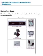
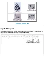
Page 2: ... of the required equipment before disposing of any packing materials Equipment List Model 800 or 1600 Amplifier Upper Monitors quantity as ordered Floor Monitors quantity equal to Uppers Power Cord quantity 1 Plastic wire ties 4 for each Upper Monitor Terminators 2 with Model 800 Amp or 4 with Model 1600 Amp ...

Page 3: ...d all of these safeguards before operating the unit Follow all warnings placed on the unit and adhere to the operating and use instructions Retain your manual for future reference 1 Power sources Connect the unit to a power source only of the type described in the operating instructions or as marked on the appliance 2 Power cord protection Route all power supply cords so that they are not walked o...

Page 4: ... if used at extreme temperatures The ideal temperature is 41oF 5oC to 87oF 30oC 7 Heat The unit should be located away from heat sources such as radiators heat registers stoves etc 8 Electric shock Care should be taken so that objects do not fall and liquid is not spilled on the enclosure If a metal object such as a hairpin or a needle comes in contact with the inside of this unit a dangerous elec...

Page 5: ...allen or liquid has been spilled into the unit C The unit has been exposed to rain D The unit does not appear to operate normally or exhibits a marked change in performance or E The unit has been dropped or the enclosure damaged 15 Servicing The user should not attempt to service the unit beyond that described in this manual All other servicing should be referred to a qualified technician Safety P...

Page 6: ...rably Line Out If you are using televisions with Audio Out the external speakers should be turned off and the volume set to the highest level Televisions should be arranged so that every user has a clear view of all televisions Stagger the rows of cardio equipment placing shorter pieces e g recumbent bikes in front and taller pieces e g steppers toward the back Tuners or receivers may be used If y...

Page 7: ... mounting holes or adhered to the floor using a strong double sided cloth tape Cabling and Connectors DO NOT SUBSTITUTE ANY TYPE OF CABLE OR CONNECTOR OTHER THAN THAT SPECIFIED BY THE MANUFACTURER The Coax Cabling and the Floor Monitors can be installed under the floor either in a sub floor or in a conduit In lieu of a sub floor or conduit use an above floor conduit system to protect the cabling s...

Page 8: ...ximum of 20 Upper Monitor sets can be connected on a single Coax line The system is designed to work with the monitor boxes connected in a daisy chain or serial configuration DO NOT CREATE BRANCHES OFF A MAIN LINE See drawing below Click here to go back to the Index Controls and Indicators ...

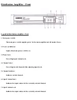
Page 9: ...on Indicator Lights when main power switch is on 3 Phone Jack For setting input volume levels 4 Channel Select For setting desired channel while adjusting input levels 5 Channel Indicator Indicates current channel 6 Input Volume Select Indicates the input volume for the currently selected channel 7 Input Volume Level Indicates the input volume for the currently selected channel ...

Page 10: ...nnector The power input connector brings 110 Vols 60 Hz AC into the system 2 Main Line Fuse Main system fuse for the amplifier and all monitor boxes 2 Amp 250 Volt Slow Blow 3 Output 1 Circuit Breaker Power to output connectors A B 2 Amp 4 Output 2 Circuit Breaker Power to output connectors C D 2 Amp 5 P A Public Address Input External paging system tie in 6 Audio Inputs ...

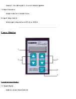
Page 11: ...8 channel amplifier 7 Output Connectors Output connectors to monitor boxes 8 Input Voltage Selector Selects input voltage between 110VAC or 220VAC Upper Monitor Legend for Upper Monitor 1 Channel Display Indicates current channel selected ...

Page 12: ...sired listening volume 4 Mute Audio mute 5 Headphone Jack Standard 3 5 mm headphone jack Floor Monitor Legend for Floor Monitor Box 1 Phone Jack Connector for Coiled Cable to Upper Monitor 2 BNC Connector Connector for attaching Coax Cable to Floor Monitor Click here to go back to the Index ...

Page 13: ...mplifier NOTE MAKE ALL CONNECTIONS TO MAIN AMPLIFIER UPPER MONITORS AUDIO DEVICES WITH POWER OFF Step 1 Connect the audio components to inputs 1 through 16 for a 16 channel Amplifier or to inputs 1 through 8 for an 8 channel Amplifier ...

Page 14: ...l system For example On a system with 40 Upper Monitors install 10 on each Coax Line 20 on each Coax Line for an 8 channel system Step 3 Connect to the optional Public Address input as follows Terminals 1 and 2 to the activation switch on the PA Terminals 3 and 4 are line level from the PA System Step 4 Use the power cord supplied to connect Main Amplifier to a 110 or 220 Volt AC outlet as applica...

Page 15: ...ep 2 Connect the T Connectors at each location to the Floor Monitor Step 3 Use the Coiled Cables to connect each Floor Monitor to an Upper Monitor Note The plug for the Coiled Cable is on the back of the Upper Monitor Step 4 On the last T Connector of each run of Coax Cable a Terminator supplied with this system must be installed for proper operation ...

Page 16: ...re This method is the preferred method of attaching the Upper Monitor to minimize interference with control panels and displays For equipment with flat control panels but no hand rails SuperLock a form of super strong velcro may be used Determine the best mounting position Clean the mounting surface thoroughly Remove the protective cover from the adhesive strip Position the Upper Monitor and press...

Page 17: ...mponent connected Step 1 When installation is complete turn power on at the Main Amplifier and all audio components The Power LED and Input Signal Bar Graph will light for 5 seconds while the display shows the version number Step 2 Plug headphones into the phono jack located under the Main Power Switch ...

Page 18: ...ssage in a song wait for a normal signal before proceeding Step 4 Use the Input Volume Select buttons to adjust the input volume level right side of display While observing the Input Signal Bar Graph adjust the input volume level as high as possible without lighting the red LEDs Observe the setting for approximately 30 seconds with a normal volume signal to insure ...

Page 19: ... at the monitor boxes These settings are automatically set in memory and retained when power is turned off Click here to go back to the Index Setup and Operation Continued Upper Monitor Operation Channel Select Press Channel Select buttons for desired channel selection left side of display Press and hold either button to scroll through channels rapidly ...

Page 20: ...ess and hold either button to adjust volume rapidly Volume automatically resets to a default volume when headphones are unplugged Mute Press Mute button to turn audio volume on or off Mute automatically resets when headphones are unplugged Click here to go back to the Index ...

Page 21: ...nsions Width 19 00 483 mm Height 3 87 98 mm Depth 14 75 375 mm Weight Model 800 11 lb 5 Kg Model 1600 17 lb 7 7 Kg Floor Monitor Dimensions Width 4 52 114 8 mm Height 1 21 30 7 mm Depth 4 85 123 2 mm Weight 6 5 oz 184 g Upper Monitor Output Level Load Impedance 550mV 32 Ohm Dimensions Width 2 55 64 8 mm Height 3 93 99 8 mm Depth 0 97 24 6 mm Weight 3 oz 83 g Cabling ...

Page 22: ...J11 6 Position 6 Fill Pinned 1 to 1 Click here to go back to the Index Note Cardio Theater Inc follows a policy of continuous advancements in development For this reason specifications may change without notice For questions regarding any specifications please call the Service Center at 800 776 6695 ...

Reviews: