background image

User Manual: xr100+_eng


5

Cardioline S.p.A.

  Via Linz,151 

38121 Trento (TN) 

info@cardioline.it  

www.cardioline.com

Sales office:


Via F.lli Bronzetti, 8  20129 Milano (MI) Italy  tel.+39 02 94750470 

fax +39 02 94750471

xr100+

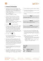
1 General Information

•  The product xr100+ bears the CE marking CE-0123 

(Notified Body: TÜV), indicating its compliance with the 
provisions of the Council Directive 93/42/EEC about 
medical devices and fulfills the essential  requirements 
of Annex I of this directive. 
The CE marking covers only the accessories listed in the 
Order Information chapter. 
The device is an MDD class IIa product.

•  The device fulfills the requirements of standard 

EN 60601-1 “Medical electrical equipment, Part 1: 
General Requirements for Safety” as well as the 
in terference protection requirements of standard 
EN 60601-1-2 “Electromagnetic Compatibility – 
Medical Electrical Devices”. 
The radio-interference emitted by this product is within 
the limits specified in EN 55011, class B.

•  The symbol 

  means: protection class II.

•  This manual is an integral part of the device. It should 

be available to the device operator at all times. Close 
observance of the information given in the manual 
is a prerequisite for proper device performance and 
correct operation and ensures patient and operator 
safety. Please note that information pertinent to sever-
al chapters is given only once. Therefore carefully read 
the manual once in its entirety.

•  The symbols 


 mean: 

 
Consult accompanying documents. 
They indicate points that are of particular importance 
in the operation of the device.

•  Observance of the safety information protects from 

injuries and prevents inappropriate use of the device. 
All device users and persons responsible for assembly, 
maintenance, inspection and repair of the device must 
read and understand the content of this manual, before 
using or working with it. Paragraphs with special sym-
bols are of particular importance.

•  If unauthorized individuals open the control terminal, 

damaging the calibration sticker, any warranty claim 
shall become void.

•  This manual reflects the device specifications and 

applicable safety standards valid at the time of printing. 
All rights are reserved for devices, circuits, techniques, 
software programs, and names appearing in this manual.

•  On request ergoline will provide a Field Service Manual.

•  The ergoline quality management system complies with 

the standard EN ISO 13485: 2012.

•  The safety information given in this manual is classified 

as follows:

Danger

indicates an imminent hazard. If not avoided, the hazard will 
result in death or serious injury.

Warning

indicates a hazard. If not avoided, the hazard may result in 
minor injury and/or product/property damage.

Caution

indicates a potential hazard. If not avoided, the hazard may 
result in minor injury and/or product/property damage.

•  To ensure patient safety, the specified measuring 

accuracy, and interference-free operation, we recom-
mend using only original ergoline accessories. The user 
is responsible if accessories from other manufacturers 
are used.

•  ergoline is responsible for the safety, reliability, and 

performance of the device, only if
—  modifications and repair are carried out by ergoline 

GmbH or by an organization expressly authorized 
by ergoline GmbH.

—  the device is used in accordance with the instruc-

tions given in this operator’s manual.

ergoline GmbH

Lindenstraße 5

72475 Bitz

Germany
Tel.: 

+49-(0)-7431 - 9894 - 0

Fax: 

+49-(0)-7431 - 9894 - 128

e-mail: info@ergoline.com

http: www.ergoline.com

Summary of Contents for xr100+

Page 1: ...User s manual xr100 xr100BP...

Page 2: ......

Page 3: ...ve the right to modify the design and technical features of the device and are not bound by the information and illustrations provided in this manual All trademarks appearing in this document are trad...

Page 4: ...r Manual xr100 _eng Cardioline S p A Via Linz 151 38121 Trento TN info cardioline it www cardioline com Sales office Via F lli Bronzetti 8 20129 Milano MI Italy tel 39 02 94750470 fax 39 02 94750471 x...

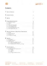
Page 5: ...4 7 Connecting the Blood Pressure Cuff 13 4 8 Connecting the SpO2 Sensor 13 5 Preparing the Patient for Blood Pressure Measurements 14 5 1 Cuff Size 14 5 2 Microphone Position 14 5 3 Applying the Cuff...

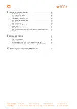
Page 6: ...f 30 8 2 1 Removing the Microphone 30 8 2 2 Cleaning 30 8 2 3 Disinfection 30 8 2 4 Inserting the Microphone 31 8 3 Maintenance 31 8 3 1 Checks before each use 31 8 3 2 Technical Safety Inspections In...

Page 7: ...opriate use of the device All device users and persons responsible for assembly maintenance inspection and repair of the device must read and understand the content of this manual before using or work...

Page 8: ...reading is unstable If the displayed value changes fre quently even though the speed is above 30 RPM this may be due to electro magnetic interference Warning Shock Hazard When the ergometer is connect...

Page 9: ...does not build up in the cuff within a reasonable period of time the measurement will be aborted and the cuff deflated If a valid measurement cannot be completed within 120 seconds the measurement wil...

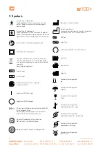
Page 10: ...umber n chster Pr ftermin gem ss MPBetreibV 20 2 1 2 2 1 9 18 17 01 02 03 0 4 0 5 06 07 08 0 9 1 0 1 1 12 Scheduled date of the next inspection e g March 2017 Toggle switch ON voltage Toggle switch OF...

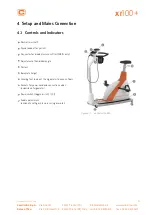
Page 11: ...4 1 Controls and Indicators 1 Control terminal P 2 Speed readout for patient 3 Connector for blood pressure cuff xr100BP only 4 Adjustment of handlebar angle 5 Castors 6 Baseplate large 7 Leveling fe...

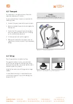
Page 12: ...on the castors only and is balanced It is now possible to transport the ergometer When you have reached the new location lower the ergometer very carefully to protect it from considerable damage Cauti...

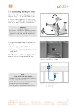
Page 13: ...to the ratings on the type plate The type plate is located on the back of the ergometer at the bottom Figure 4 4 Assembly position The connection panel is located on the underside of the ergometer Co...

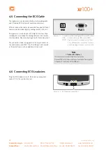
Page 14: ...lity Please contact ergoline for these adapters The connection cable is plugged into the 9 pole socket of the connection panel Port 1 or the USB port and secured at the metal frame with an additional...

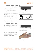
Page 15: ...refore do not forget to attach the cuff tubing to the handlebar with the supplied Velcro tape Open the large Velcro tape and wrap it around the handle bar Secure the cuff tubing with the small Velcro...

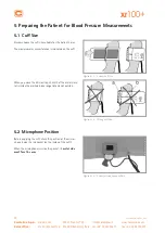
Page 16: ...ize suitable for the patient s arm The maximum arm circumference is indicated on the cuff Figure 5 1 Correct cuff size When you close the Velcro strap check that the metal clasp a is inside the marked...

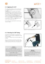
Page 17: ...ff position tab 5 4 Checking the Cuff Tubing Check that the cuff tubing does not knock against the patient s knee when the patient is pedalling and the hand is on the handlebar Secure the cuff tubing...

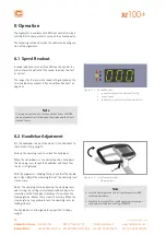
Page 18: ...dout starts blinking on the display and the load is reduced to zero 6 2 Handlebar Adjustment Set the handlebar to a position where it is comfortable to reach while sitting upright Fold up the clamping...

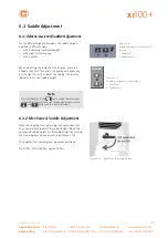
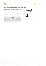
Page 19: ...y first Then press the appropriate arrow key on the right to raise or lower the saddle The display indicates the current saddle height 1 2 Saddle 0 Figure 6 4 Saddle adjustment at the display 1 Saddle...

Page 20: ...ent of the saddle height pull the lever of the gas pressure spring upward as shown in figure 6 7 The saddle moves up automatically To lower the saddle also pull the lever of the gas pressure spring up...

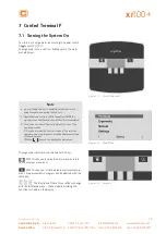
Page 21: ...sure cuff to the patient AFTER the ergometer has been turned on and the self test completed The device can be configured to default to one of the operating modes If this option is selected the start s...

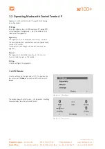
Page 22: ...required at the ergometer Ergometry The ergometer runs an automatic exercise test some of the corresponding test protocols are user configurable and stored in the system see chapter 7 2 4 Settings wi...

Page 23: ...most recent BP value systolic diastolic values or cuff pressure during inflation and bar graph indicating microphone signal strength see below 3 duration of exercise test min 4 heartrateatthetimeofth...

Page 24: ...t Figure 7 9 Selecting an exercise test protocol The exercise test is started with the Start key a blood pressure measurement at rest may precede the test depending on selected ergometry protocol When...

Page 25: ...softkeys on the right and left to position the bar cursor on Manual and confirm the selection with Select In this operating mode the user controls the entire exercise test by selecting the loads stage...

Page 26: ...e parameter to change and confirm the selection with Select Figure 7 17 Settings Menu Default Mode In this menu you choose the default mode activated when the ergometer is turned on When first turned...

Page 27: ...0 Selecting the parameter to edit All other parameters are edited in the same way Using the arrow keys highlight a parameter and confirm the selection with Select the corresponding value appears in re...

Page 28: ...nu Beep The audio signal emitted during blood pressure measure ments can be turned on and off Figure 7 25 Beep during BP measurements Software Version Select this option to view the installed software...

Page 29: ...d level the ergometer generates a control pulse and sends the corresponding data via the interface Analog Digital An analog voltage controls the load blood pressure measurements can be initiated with...

Page 30: ...with Select Using the arrow keys change the value and save the new value with Select Figure 7 30 Setting the RPM limit values Note The limits selected in this menu only apply to the load range betwee...

Page 31: ...alcohol Warning Shock Hazard Disconnect the device from the power line before cleaning Equipment Damage Do not allow liquids to enter the equipment Devices into which liquids have entered must be imme...

Page 32: ...agents containing alcohol Clean the microphone with a cloth moistened with alcohol or soap water Allow the microphone to dry before reinserting it in its pocket Warning Equipment Damage Cuff micropho...

Page 33: ...before it can be used again 8 3 2 Technical Safety Inspections Inspections of the Measuring System The technical safety inspections and the inspections of the measuring system must be completed every...

Page 34: ...urrent brake with torque mea surement speed independent to DIN VDE 0750 0238 Load range 6 999 Watt speed RPM independent see diagrams on page 35 Speed range 30 130 n min Load accuracy to DIN VDE 0750...

Page 35: ...rom PC driver required Dimensions weight length 1030 mm width 490 mm width of handlebar approx 530 mm height 1140 to 1400 mm weight approx 66 kg Safety standards DIN EN 60601 1 DIN EN 60601 1 2 DIN VD...

Page 36: ...pressure 40 to 280 mmHg pulse rate 35 to 230 bpm Measurement error systematic systolic pressure 3 mmHg diastolic pressure 3 mmHg temperature 15 to 25 C Standard deviation clinical trial systolic diast...

Page 37: ...ry Time min 1 WHO 25 2 25 25 99 2 BAL 50 3 50 25 99 3 Hollmann 30 3 40 25 99 4 STD France 30 3 30 25 99 5 Standard 20 1 25 25 99 6 15 user programmable 25 2 25 25 99 Adjustment Range 20 100 1 30 1 400...

Page 38: ...ne it www cardioline com Sales office Via F lli Bronzetti 8 20129 Milano MI Italy tel 39 02 94750470 fax 39 02 94750471 xr100 9 5 Family of characteristics of the load periods according to IEC 60601 1...

Page 39: ...other equipment If adjacent or stacked use is necessary the equipment or system should be tested to verify normal operation in the configuration in which it is being used Guidance and Manufacturer s D...

Page 40: ...sed Mains power should be that of a typical commercial or hospital environment Surge to EN 61000 4 5 1 kV differential mode 2 kV common mode 1 kV N A Mains power should be that of a typical commercial...

Page 41: ...transmitter manufacturer and d is the recommended separa tion distance in meters m Field strengths from fixed RF trans mitters as determined by an elec tromagnetic site survey a should be less than t...

Page 42: ...mended below according to the maximum output power of the communications equipment Rated Maximum Output Power of Transmitter W separation distance according to frequency of transmitter m 150 kHz to 80...

Page 43: ......

Page 44: ...Via Linz 151 38121 Trento TN ITALY e mail info cardioline it web www cardioline com 201000528000 2018 12 06 Rev 03 Englisch...

Reviews: