


EX
90
17
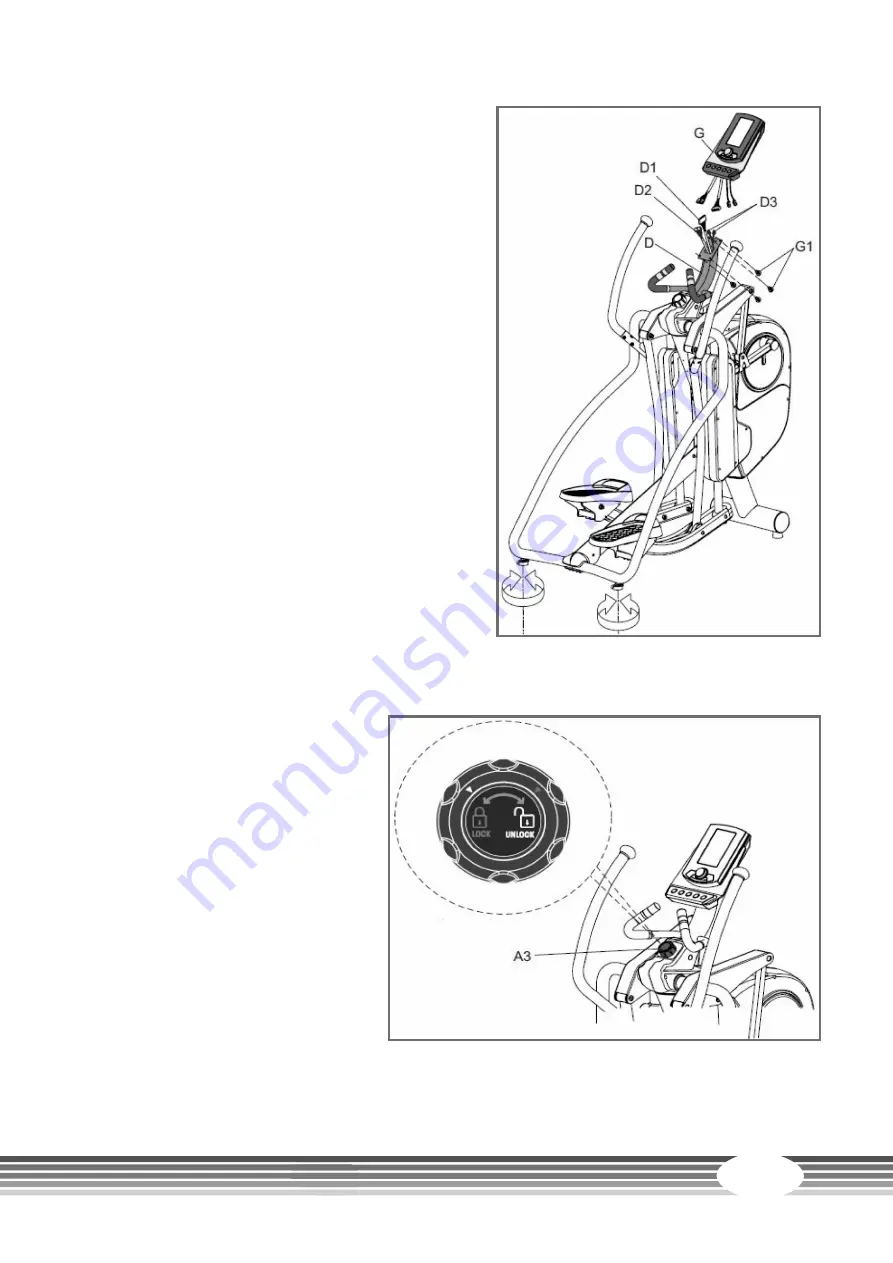
Step 8:
Assembly of the console and adjusting the supporting feet
1. Loosen the four pre-mounted screws (G1) from
the console (G).
2. Connect the console cables (D1 and D2) and the
heart rate cables (D3) from the console mast with
the console.
L
NOTICE
Make sure that the cables are properly connected
with each other. Slide the excess cable into the
casing and the console mast (D).
3. Mount the console (G) on the console mast (D)
with the four screws (G1).
4. Use the adjusting screws under the side parts in
order to level out the unevenness in the floor.
Step 9:
Locking the pedal bars (B1 and B2)
⚠
CAUTION
+
The pedal bars should
always be locked, when the
equipment is not in use.
+
Never lock the pedal bars,
when the equipment is still
moving, but only when the
equipment has come to a
complete standstill.
To do this, turn the knob (A3) to the
“LOCK” position in order to lock the
pedal bars (B1 and B2) and to avoid
possible injuries.
Summary of Contents for CST-EX90
Page 2: ...EX90 2...
Page 40: ...EX90 40 8 3 Exploded Drawing...
Page 41: ...41...
Page 46: ...EX90 46...
Page 47: ...47...
Page 48: ...Elliptical cross trainer EX90...


