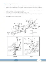
13
15
16
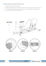
13
15
16
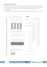
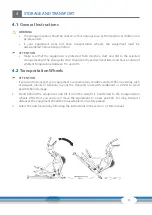
6 m/m
17
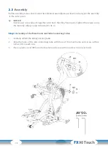
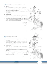
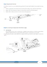
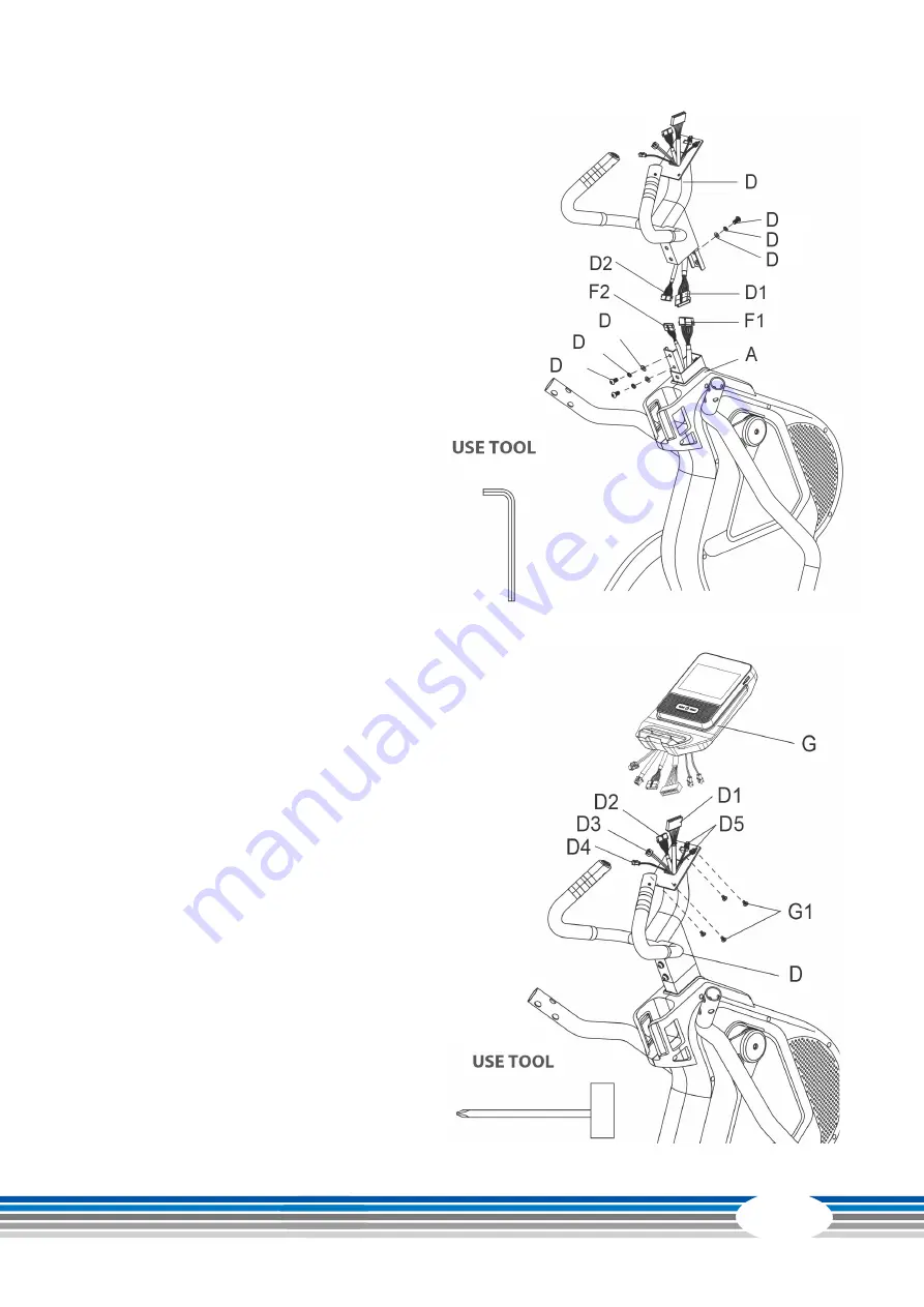
Step 4:
Assembly of the Console Supporting Tube
L
NOTICE
The pre-installed screws (D12), spring washers (D14)
and washers (D15) need to be removed before inserting
the console supporting tube (D).
1. Connect the cables D1 and A1 as well as D2 and A2 with
one another.
࣑
ATTENTION
Make sure not to pinch the cables during the following
step.
2. Insert the console supporting tube (D) into the main
frame (A) and secure with the previously removed
screws (D12) and washers (D14 & D15).
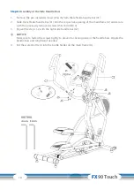
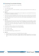
Step 5:
Assembly of the Console
1. Remove the four screws (G1) from the back of the
console (G).
2. Connect the cables of the console supporting tube
(D1, D2, D3, D4, D5) with their respective counterparts
of the console (G).
࣑
ATTENTION
Make sure not to pinch the cables during the
following step.
3. Carefully push excess wire into the console supporting
tube (D).
4. Mount the console (G) to the console supporting
tube (D) with the previously removed screws (G1),
hand tightening first.
Summary of Contents for CST-FX90-T
Page 2: ...2 FX90 Touch...
Page 45: ...45 Notes...
Page 46: ...46 FX90 Touch Notes...
Page 47: ...47...
Page 48: ...Crosstrainer FX90 Touch...


