M8x1.25x15L
D16xD8.5x1.2T
x2
x2
x2
D15.4xD8.2x2T
ST4.2x15L
M5x0.8
x
10L
x2
x2
88
89B
110 114 93
92
89A
132
25
31 8 11
88
89A
89B
25
132
31
8
11
31
8
11
Step3
132
25
1
42
52L
52R
42
M5x0.8x15L
x6
15
Step 3:
Assembly of the console
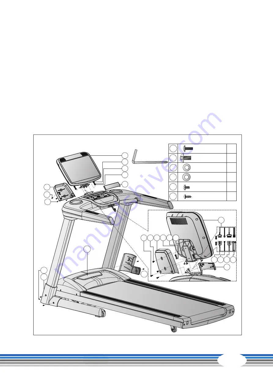
1. Connect the cables (
92
,
93
,
110
and
114
) with their counterparts of the console (
88
).
࣑
ATTENTION
Be careful not to pinch the cables in the following step.
2. Fix the console (
88
) to the handlebar (
4
) with two allen bolts (
31
), two flat washers (
11
) and two
spring washers (
8
).
3. Fix the console cover (
89B
) to the console (
88
) with two cross bolts (
132
).
4. Attach the decorative cover (
89A
) with two screws (
25
).
5. Now tighten the bolts (
7
) from
step 1
.
6. Attach the two covers for the handlebar post (
52L
and
52R
) with six bolts (
42
).
Summary of Contents for CST-TX90-2-HD
Page 2: ...2 TX90...
Page 44: ...44 TX90 8 3 Exploded Drawing...
Page 49: ...49 Notes...
Page 50: ...50 TX90 Notes...
Page 51: ...51...
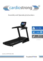
Page 52: ...Treadmill TX90...

