background image

UI SmartSeatPro 

II

 User Guide. Iss1 06/22

28

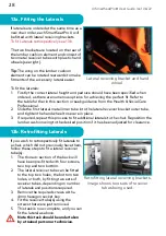
If laterals are ordered at the same time as a 

new chair order, each SmartSeatPro 

II 

will 

be fitted with lateral receiving brackets. 

To fit Laterals retrospectively see 13b.


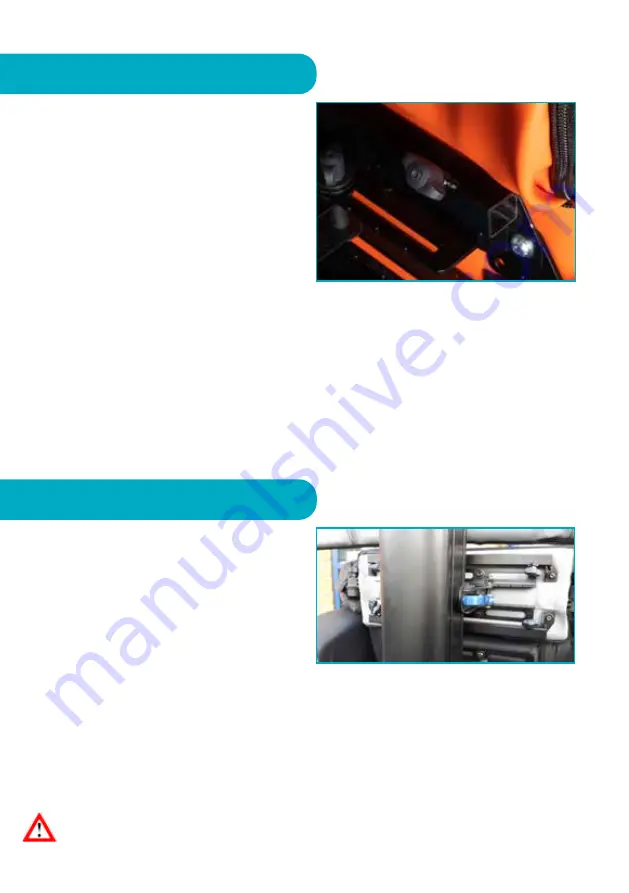
The two brackets are located on the rear of 

the lumbar cushion element and consist of 

two metal receiver tubes with plastic hand 

wheels (see right). 

Tip: The wing on the lumbar cushion 

element can be rotated rearwards to make 

fitments of the accessory lateral easier. 

To fit the laterals: 

1.  Firstly the correct lateral height and pad size should have been specified when 

ordered, as there are numerous options for achieving the perfect fit. Refer to 

the table further in this section or seek guidance from the Health & Social Care 

Professional.

2.  Slide the first lateral metal inner tube into the lateral receiver bracket outer tube, 

and tighten the hand wheel to secure in place. 

3.  If required, repeat this process to fit additional laterals to the chair. Reposition the 

lumbar cushion wing to the desired position if it has been adjusted for clearance.

13a. Fitting the Laterals

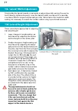
If you wish to retrospectively fit laterals to 

a chair, which did not previously have them, 

follow these steps to fit a lateral receiver 

tube(s):

1.  The thoracic section of the back will 

have been pre-fitted with four screws, 

two top and two bottom.

2.  The lateral receiver tube can be fitted 

to the top two holes, the bottom two 

holes, or both, by fitting two sets of 

receiver tubes, depending on number 

of laterals and positions required.

3.  Remove the required screws with a 

4mm hexagon socket key.

4.  Fit the receiver tube(s) using the 

screws that were just removed.

5.  This task is now complete, and you can 

fit the lateral as above.

• 

Note this task should be undertaken 

by a trained person or technician.

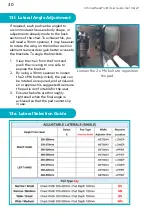
Lateral receiving bracket and hand 

wheel.

13b. Retrofitting Laterals

Retrofitting lateral receiving brackets, 

image shows two sets of receiver 

tubes being used.

Summary of Contents for SmartSeatPro II

Page 1: ... modular chair has evolved taking specialist seating to a whole new level This seating system is highly adjustable and adaptable for individuals with complex posture and pressure management needs WARNING A level of supervision appropriate to the user s abilities should be applied at all times Medical Device Class 1 ...

Page 2: ...rmrest Height Removal 14 Seat Cushion 15 Seat Width 16 Seat Depth 17 Seat Height 18 Back System Configurations Options 20 Back Adjustments 22 Head Wing Adjustments 24 Headrests Accessory 26 Pommel Accessory 27 Lateral Accessory Selection Guide 31 Tray Accessory 32 Positioning Aids Accessory 26 Battery Motorised Option 37 Looking After Your Chair Safety 38 Maintenance Servicing 39 Identification La...

Page 3: ...t seating to the next level for those with complex postural management and pressure care needs The SmartSeatPro II s unique design allows for a range of configurations to ensure postural asymmetries can be fully stabilised accommodated and where possible corrected from the feet through the pelvis and spine and to the head The SmartSeatPro II benefits from Tilt in Space Back Angle Recline and a mul...

Page 4: ...cal Drawings All measurements 10mm 5 Weights Kilograms Chair Weight Manual Standard Specification 77kg Chair Weight Manual Ratchet Arm Option 85kg Chair Weight Motorised Standard Specification 83kg Chair Weight Motorised Ratchet Arm Option 91kg Maximum User Weight 160kg ...

Page 5: ...URES New Multi Adjustable and Modifiable Back and Head System Tilt in Space with New Inclinometer Visual Tilt Angle Indicator Back Angle Recline with New Visual Indicator WaterCell Technology New Increased Negative Angle Channelled and Elevating Leg Rest New Angle Adjustable Flip Up Footplate New Integral Seat Depth Adjustment New Integral Seat Width Adjustment New Integral Arm Height Adjustment N...

Page 6: ... as stable as possible The chair is fitted with four fully braked castors and at least TWO of the castors should be engaged with brakes on prior to transfer To lock the brakes position the chair approximately where you need it to be for transfer Gently push the chair away from you so that the castors swivel around and the blue brake levers can be easily accessed Press down the end of the brake lev...

Page 7: ...i disciplinary team where indicated In some cases this function will be contra indicated A 2 Tilt in Space The SmartSeatPro II chair has a Tilt in Space function which allows the user to be tilted without adjusting the critical angles for sitting at the hips and knees This helps the user to maintain a stable sitting posture whilst redistributing their weight over a large surface area Tilt in Space...

Page 8: ...e remains the same the whole system tilts posteriorly Promotes pelvic stability Encourages pressure redistribution Manages energy levels Assists with hoisting and positioning Tilt angle will be dependent on safety tolerance and appropriateness The new informative inclinometer A will aid seating prescription and safe use A ...

Page 9: ... Angle Recline adjustment B 3 Back Angle Recline The SmartSeatPro II chair has a Back Angle Recline function which is used to adjust the angle between the seat and the back thus opening closing the hip angle Always warn the user before changing the Back Angle Recline setting to ensure that they do not become distressed or agitated which can affect postural stability The chair back angle can be adj...

Page 10: ...gle adjusts to open up the hip angle Assists with comfort and reduces abdominal pressure Accommodates reduced hip flexion range of movement and helps alleviate any associated pain Back angle will be dependent on hip range of movement and pelvic stability The visual back angle indicator A for degree of recline will aid seating prescription and safe use A ...

Page 11: ...he leg rest elevation is controlled by the handset The top row of two buttons control the elevation The left hand button raises the leg rest and the right hand button lowers the leg rest 3 Leg Rest The SmartSeatPro II has an integral leg rest which can be elevated to support the legs The leg rest mechanism articulates following the movement of the knee as it elevates the legs The leg rest incorpor...

Page 12: ...t the footplate height is reduced by hand every time the leg rest is lowered The footplate can be adjusted and set to a choice of 4 positions 75 90 105 120 This equates to a 120 range of adjustment In all angled positions the footplate can be easily lifted up to 0o vertical to move it out of the way The SmartSeatPro II footplate angle can be adjusted to correct positioning at the feet to neutral o...

Page 13: ...rofessional The armrests A can be removed to aid user transfers positioning cleaning and servicing 1 Locate the two quick release levers one is located at the front of the seat base and one at the rear 2 Pull in an upwards motion to loosen 3 The armrest can then be removed The armrest can be removed completely for side transfers 5a Ratchet Height Adjustment Armrest Upgrade CareFlex offers an upgra...

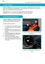
Page 14: ...y be necessary to remove the seat cushion to access parts of the chair and for cleaning and replacing the cushion To remove the seat cushion 1 Unlock the cam lock buckles on the front of the seat and pull the straps through 2 Detach the Velcro connecting the leg rest to the underside of the seat module 3 Unclip the two plastic J clips at the back and pull them out of the slot 4 Now remove the seat...

Page 15: ...d lower limb postures such as wind sweeping or those with increased body mass in the gluteal and hip areas This may cause some superficial damage to the seat width stickers if undertaken without care If required over time the quick release levers can be tightened or loosened by holding the lever in an unlocked position and turning the nut clockwise to tighten anti clockwise to loosen The SmartSeat...

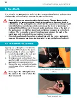
Page 16: ...tting and to achieve the best distribution of weight between the user and the chair Sacral sitting occurs when the pelvis tilts backwards The sacral area can be susceptible to pressure problems Sacral sitting will occur if the seat depth is set too long If the seat depth is too short then the area over which body weight is distributed may be reduced which can increase the risk of pressure injury S...

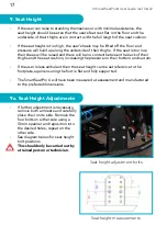
Page 17: ...heir thighs and the seat cushion increasing the pressure on their bottom and sacrum If the user is less ambulant then the seat height can be set reference to the footplate again ensuring the foot is flat and fully supported The SmartSeatPro II will have been measured at assessment and manufactured to the preferred dimensions 9a Seat Height Adjustments If further adjustment is necessary remove both...

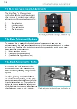
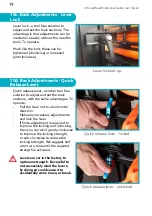
Page 18: ... CareFlex offer three back section fixing methods which would have been specified on assessment 1 Bolts standard option 2 Lever Lock upgrade option 3 Quick Release upgrade option 10b Back Adjustments Bolts As standard the back sections will be fixed to the centre pillar with M6 bolts these can be adjusted by using a 10mm spanner To adjust partially loosen the bolts in an anticlockwise direction se...

Page 19: ...h the same advantages To operate Pull the lever out to a horizontal direction Make any necessary adjustments and lock the lever If finite adjustment is required to improve the locking and unlocking then you can wind gently clockwise to improve the locking strength or anti clockwise to reduce the locking strength We suggest half a turn at a time until the required strength is achieved Levers are se...

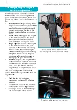
Page 20: ...f the cushion element and twist upwards or downwards assuming there is space above or below to set the desired angle before locking into place Note Ensure the pivot points are sufficiently loosened to disengage the gear mechanism Rotation support the weight of the cushion element and with one pivot point locked and the other loosened twist to set the desired rotation angle before locking back into...

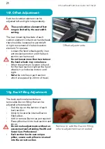
Page 21: ...n the optimum location is found for the back section tighten the hand wheels in a clockwise motion until tight Note the notches in each section which are spaced by 20mm of travel Offset adjustments 10g Back Filling Adjustment The back cushion elements have removable Dacron filling that can be adjusted where needed Find the zip on the bottom of each back section Unzip to locate the internal Dacron ...

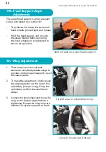
Page 22: ...tment 1 The thoracic and cervical back elements include adjustable wings to provide contouring and support to suit the user s needs 2 To make the adjustment firstly locate the zipped aperture at the rear of the upholstery one per wing Unzip the upholstery and find the small hand wheel 3 Loosen the hand wheel and move the wing to the desired angle before re tightening Ensure the wing is secure and ...

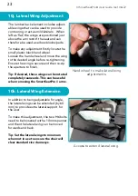
Page 23: ... and then re zip the aperture to finish Tip If desired these wings can be rotated completely rearwards This can be useful when removing the SmartSeatPro II arms 10j Lateral Wing Adjustment Hand wheel to make lateral wing adjustments Access to extend lateral wing In addition to being adjustable for angle the lateral wings can be extended by 60 mm to provide extra lateral support for the user To mak...

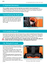
Page 24: ...el The pommel is designed to separate the knees and support the whole inside of the knee joint For this reason the pommel is not depth adjustable and sticks out in front of the seat edge A pommel should never be used as a restraint and the user must not be allowed to slide into the sacral sitting position resting against the pommel 12 Pommel Accessory Fit the pommel with the leg rest angled downwa...

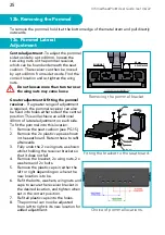
Page 25: ...iver If a greater range of adjustment is required the pommel receiver can also be fixed into holes either side of the central position This will achieve an additional 40mm of lateral adjustment on each side To fit the pommel into this location 1 Remove the seat cushion see PG 15 2 Remove the 2 x plastic caps as shown in the seat board Retain these to refit afterwards 3 Fully undo the 2 x wing nuts...

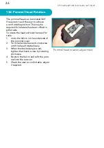
Page 26: ...offset to either side To rotate the head without the need for tools 1 Undo the Velcro on the underside of the pommel cover 2 Turn the hand wheel anti clockwise until the head rotates freely 3 When the desired angle is set tighten the thumb screw by twisting clockwise 4 Re stick the Velcro and refit the pom mel into the receiver 5 Check the user is comfortable adjust if required Pommel head rotatio...

Page 27: ...ge of 200mm 400mm chest width Narrow 300mm 500mm chest width Wide Depth Two pad sizes and depth options to accommodate various body shapes 160mm Small 190mm Medium A kidney shaped pad is also available The objective of using supports like adjustable laterals is to position the user as upright and as close to a midline position as possible so that pelvis spine and head are aligned in a vertical col...

Page 28: ...el to secure in place 3 If required repeat this process to fit additional laterals to the chair Reposition the lumbar cushion wing to the desired position if it has been adjusted for clearance 13a Fitting the Laterals If you wish to retrospectively fit laterals to a chair which did not previously have them follow these steps to fit a lateral receiver tube s 1 The thoracic section of the back will ...

Page 29: ... By using a 10mm spanner to loosen the 2 x M6 bolts A the pad can be repositioned Three steps are available each representing 20mm of movement Ensure the 2 x M6 bolts are tightened prior to use It may be easier to rotate the wing on the lumbar cushion element rearwards to gain better access to the brackets 3 Each lateral can if desired be rotated by 180 and fitted on the opposite side of the chair...

Page 30: ...ards to gain better access to the brackets To angle the brackets 1 View the chair from the front and push the covering to one side to expose the bracket 2 By using a 10mm spanner to loosen the 2 x M6 bolts circled the pad can be rotated as required and a trial and error approach is suggested to ensure the pad is comfortable for the user 3 Ensure the bolts are thoroughly tightened when the final an...

Page 31: ...14 Tray Accessory SmartSeatPro II tray If a chair is ordered with a tray the chair will be fitted with the appropriate attachment straps If a tray is ordered separately then attachment straps will need to be fitted to the chair To attach the tray straps to the armrest 1 Remove each arm from the chair and lay down 2 Remove the 2 x caps from the inside of the arm and discard 3 Fit the two straps KIT...

Page 32: ...on must be provided for all those who use them Please read the disclaimer on page 38 15 Positioning Aids Accessory Pelvic belts are attached to the anchor bars on the rear bottom edge of the back frame Fit two x HAR0093 tri glide adjusters one per strap on each side of the belt Loop each strap through the rear slots in the back of the chair as shown Tighten using the tri glide as required To faste...

Page 33: ... M6 x 30mm button head screw 2 x M6 washers 1 x M6 nylon nut for each one Unless the belt has been purchased retrospectively these will have been factory fitted 6 Loop the straps exactly as shown securely and tighten The belt must be started from the inside slot and work outwards to ensure the mounting plate cannot weaken 7 To fasten the buckle click two halves together 8 To release buckle press t...

Page 34: ...lder straps through the back metalwork and fix with 2 x clip locks as shown 4 The dynamic chest harness is held in position with a strap from each corner two straps attach at the users waist and two over their shoulders 5 These straps are attached to the harness with cam lock buckles the length of the straps can be adjusted through the buckles Always ensure the harness is positioned correctly and ...

Page 35: ...wer cushion to the seat cushion 2 The harness consists of a neoprene cross shape and webbing straps Two points of the padded cross shape are attached at the junction between the seat and back cushions 3 When seated in the chair the two loose ends of the harness should be pulled up over the users thighs and attached to the straps at the rear of the chair 4 The harness can be adjusted through the we...

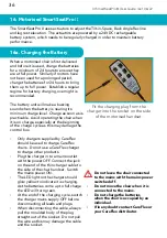
Page 36: ...e control box Only chargers supplied by CareFlex should be used to charge CareFlex chairs Do not use a CareFlex charger to charge other products Plug the charger in to a mains outlet with the power OFF Connect the jack on the end of the thin charger cable to the side of the chair handset Switch the mains power ON The LED light on the charger should glow yellow to indicate it is charging As the bat...

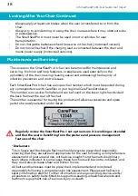
Page 37: ...ou are unsure of the chair s covering material contact CareFlex with the serial number of the chair which will allow CareFlex to trace the specification of the chair Regularly unclip the back of the seat cushion to lift the cushion up and clean the seat board around the sides of the seat cushion where food crumbs and other debris can accumulate Structural maintenance Do not attempt to carry out an...

Page 38: ...t two brakes when the user is transferred to or from the chair Always try to avoid storing or using the chair in areas where it may obstruct exits or passageways The SmartSeatPro II must never be used in motor vehicles for user transportation Do not charge the batteries when the user is in the chair motorised version Do not move the chair if the charging lead is connected between the chair and mai...

Page 39: ...UI SmartSeatPro II User Guide Iss1 06 22 39 Identification Label Notes CareFlex Chair Number ________________________________ ...

Page 40: ...o II User Guide Iss1 06 22 40 CareFlex Ltd Templer House King Charles Bus Pk Old Newton Rd Heathfield Devon TQ12 6UT Tel 0800 018 6440 www careflex co uk info careflex co uk Scan me to visit the SmartSeatPro II page ...

Reviews: