Carefree of Colorado Installation
Manual
E
CLIPSE
,
OEM
052547-021
11
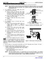
6. Measure and cut away any excess cable from the motor and exterior switch cables. Terminate the
wires and install in the mating connector as shown in Figure 13 page 12.
NOTE: As an alternate installation, cutoff the existing connector from the control box bundle and
butt splice the cable wires and relay module wires as shown in Detail A on page 10.
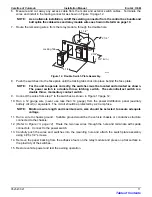
7. Route the remaining wires, from the relay module, through the double hole.
Locking Tab
1 1/2"
E0011
4 1/4"
2 3/4" (min.)
2 3/4"
O 2 1/4"
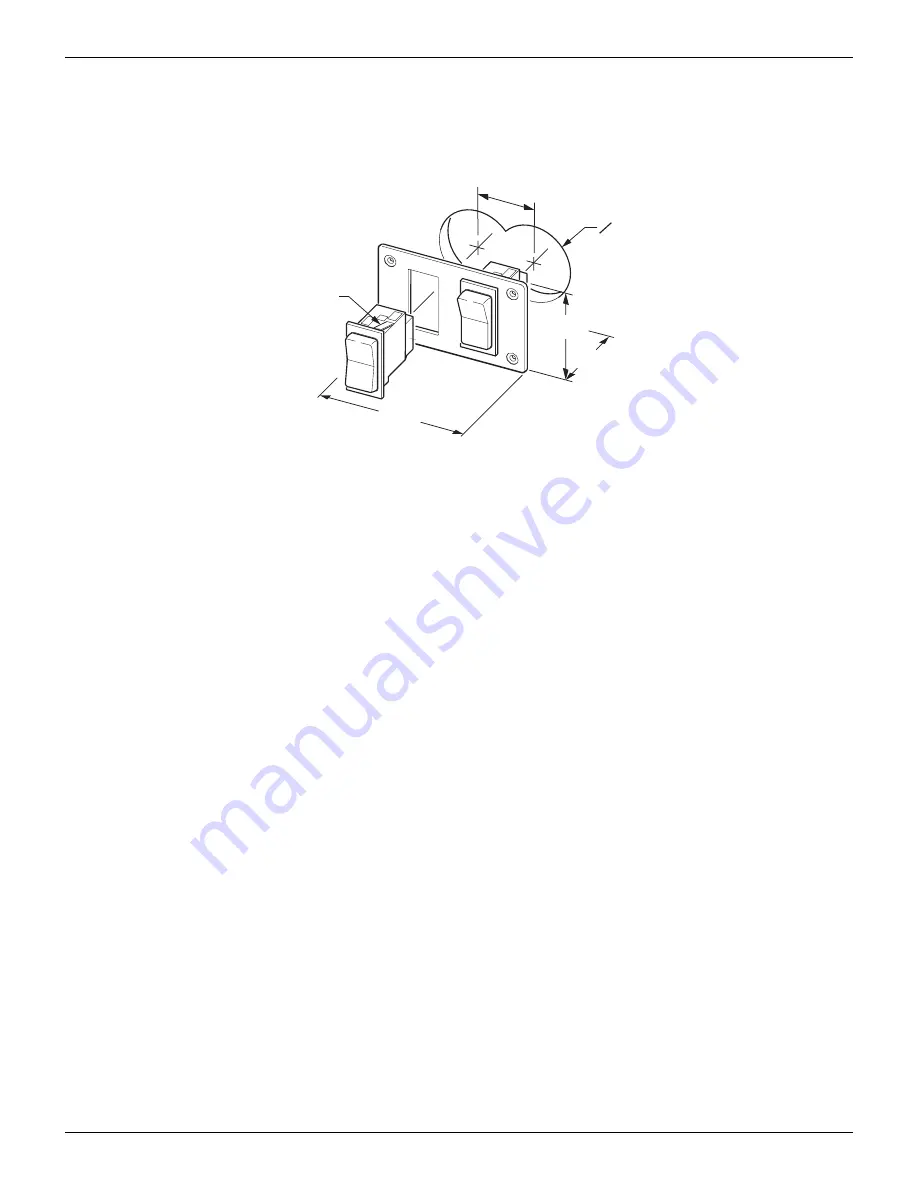
Figure 12. Double Switch Plate Assembly.
8. Push the switches into the face plate until the locking tabs click into place behind the face plate.
NOTE:
For the unit to operate correctly, the switches must be located and oriented as shown.
The power switch is a double throw, latching switch. The extend/retract switch is a
double throw, momentary contact switch.
9. Connect the wires from step 7 to the switches as shown in Figure 13 page 12.
10. Run a 12 gauge wire (never use less than 14 gauge) from the power distribution panel (auxiliary
battery circuit) or equivalent. The circuit should be protected by a 20 amp fuse.
NOTE: Minimum wire length and maximum wire size should be selected to assure adequate
voltage.
11. Run a wire to chassis ground. Suitable ground would be the vehicle chassis or conductive structure
connected to the chassis.
12.
Route the two new wires through the hole and terminate with spade
connectors. Connect to the power switch.
13. Carefully push the wires and switches into the mounting hole and attach the switch plate assembly
using 4 #6 x 1/2” screws.
14. Remove the paper backing from the adhesive foam on the relay module and press on a flat surface in
the proximity of the switches.
15. Restore vehicle power and test the awning operation.
Table of Contents


