Carefree of Colorado Installation
Manual
E
CLIPSE
,
OEM
052547-021
7
6.
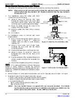
Drill a 5/32” hole at the first mounting hole and attach the motorized arm using a 1/4 x 1 1/2” lag
screw.
7.
Confirm that the arm is perpendicular to the awning rail, attach the arm at the second mounting point
(shown in Figure 5) using a 5/32” drill bit and a 1/4 x 1-1/2” lag screw.
8.
Position the roller assembly so that it is perpendicular to the motorized arm assembly. Position the
non-motorized arm perpendicular to the roller assembly.
9.
Drill a 5/32” hole at the first mounting hole and attach the non-motorized arm using a 1/4 x 1 1/2” lag screw.
10. Check the alignment; the arm assembly must be
perpendicular to the roller assembly. When the
alignment is correct, drill and attach the arm at the
second mounting hole (shown in Figure 4) using a
5/32” drill bit and a 1/4 x 1-1/2” lag screw.
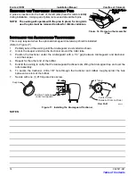
11. Hold the awning closed and carefully remove the
plastic wraps at the top of the arms. The awning
will open a few inches.
12. Cap or cover the exposed ends of the motor wires.
This is to prevent accidental shorting or
grounding during assembly.
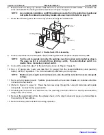
13. Open the awning about 18” or until the top mounting
holes on the arms are visible. To open
•
Use the supplied jumper cables and attach to the
emergency terminals located on the top of the
motorized head.
•
Connect the other ends of the jumper leads to a
12V source. If the awning does not begin to
move, reverse the leads.
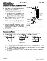
14. Using a 5/32” drill bit, locate and drill the mounting
holes.
15. Using two each 1/4 x 1-1/2” lag screws, attach the
top of the arm assemblies to the vehicle.
Upper Mounting Holes
(Arm Extended Out)
Lower Mounting Holes
1st Mounting Hole
2nd Mounting Hole
E0003
Mounting Holes
1/4 x 1 1/2 Screws Only
1/4 x 1 1/2 Screws
or
3/16 Moly Rivets
Figure 5. Arm Mounting Hole Locations.
Table of Contents


