E
CLIPSE
,
OEM Installation
Manual
Carefree of Colorado
8
052547-021
I
NSTALLATION
–
E
LECTRICAL
The Eclipse Patio Awning has two switch/wiring options. The single switch configuration has one interior
extend/retract switch. The multiple switch configuration has one power switch, one exterior extend/retract switch,
one interior extend/retract switch and a control box. The multiple switch wiring instructions start on page
Error!
Bookmark not defined.
.
NOTES:
•
Failure to follow the wiring instructions in this publication may void the motor warranty.
•
All wiring must conform to NEC (National Electrical Code) and local codes.
•
D
O NOT
wire two or more motors to one switch—No parallel wiring.
CAUTION
A
LWAYS DISCONNECT THE VEHICLE BATTERY AND ELECTRICAL SOURCES BEFORE WORKING WITH THE
ELECTRICAL WIRING AND COMPONENTS
.
S
INGLE
S
WITCH
I
NSTALLATION AND
W
IRING
1.
Determine the final location of the switch and mark the
location.
NOTE:
The switch panel must be mounted within
32 inches of the point of entry for the cable.
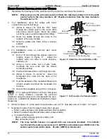
2. For installations using the cable with a direct
connection (no external plug)
2.1
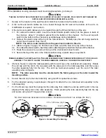
(Refer to Figure 6)
Drill a 5/16” hole through the
vehicle wall for the motor cable.
2.2 Route the cable through the holes to the location
of the switch panel.
2.3 Seal the cable and hole using a silicone sealant.
2.4 Go to step 4.
3. For installations using an external wall mount
plug/receptacle:
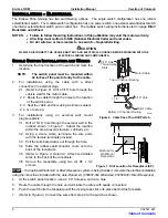
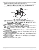
3.1 Drill a 15/16” hole through the exterior wall in the
location shown in Figure 7. Adjust the location
within the area to avoid structure, cabinetry etc.
3.2 Using a 2-wire cable, terminate the wire ends
with the female terminals provided.
3.3 Pull the terminated wires out through the hole.
3.4 Slide the rubber seal/connector cover onto the
back of the receptacle.
3.5
(Refer to Figure 9, Detail A)
Attach terminated
wires to the back of the receptacle.
3.6 Secure the receptacle using two (2) #6 x 1/2
screws.
STOP
–
If an optional Windsmart or Direct Response system is being installed, complete the electrical installation
using the instructions included with the Auto-Retract kit. (052987-002 Windsmart, 052526-001 Direct Response)
4.
At the switch panel location, use a 2 1/4” hole saw and cut a hole.
5.
Route the cable through the hole and terminate the wires with spade connectors.
6.
Push the switch into the faceplate until the locking tabs click into place behind the faceplate.
7.
(Refer to Figure 9)
Connect the wires from step 9 to the switch as shown.
5/16" Hole
Thru Existing
Slots
Top of Channel Routing
Bottom of Channel Routing
E0005
Motor Cable
1 1/2"
Motor Cable
5/16" Hole
Figure 6. Cable Pass Thru Drill Pattern.
E0033
1"
4"
3"
5"
Drill Area for
Wall Mount
Receptacle
Figure 7. Drill Location for Receptacle (EP).
Table of Contents


