E
CLIPSE
,
OEM Installation
Manual
Carefree of Colorado
10
052547-021
M
ULTI
-S
WITCH
I
NSTALLATION AND
W
IRING
1.
Determine the final layout of the switches and the control box and mark the locations.
NOTE:
When using only the wire harnesses furnished, the maximum distance from the cable
point of entry to the relay module is 48”. Maximum distance from the relay module to
the switches is 16”.
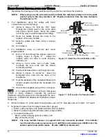
2. For installations using the cables with direct
connections (no external plug):
2.1
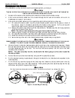
Drill two 5/16” holes
through the vehicle wall for the motor cable
and exterior switch cable. Move the cables
out of the way to avoid damage while drilling.
2.2 Route the cables through the holes to the
location of the relay module.
2.3 Seal the cables and holes using a silicone
sealant.
2.4 Go to step 4.
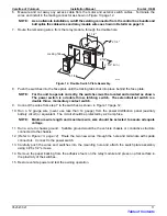
3. For installations using an external wall mount
plug/receptacle:
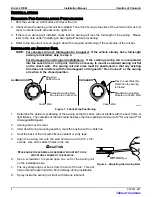
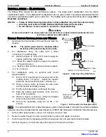
3.1 Drill a 7/8” hole through the exterior wall in the
location shown in Figure 11. Adjust the
location within the area to avoid structure,
cabinetry etc.
3.2 Using a 3-wire cable and a 2-wire cable,
terminate the wire ends with the female
terminals provided.
3.3 Pull the terminated wires out through the hole.
3.4
(Refer to Figure 13, Detail A)
Insert the
terminated wire ends into the back of the
receptacle.
3.5 Coat the backside of the receptacle flange with
silicone sealant and insert the receptacle into
the hole.
3.6 Secure the receptacle using 4 #6 x 1/2 screws.
STOP
–
If an optional Windsmart or Direct Response
system is being installed, complete the electrical
installation using the instructions included with the Auto-
Retract kit. (052987-002 Windsmart, 052526-001 Direct
Response)
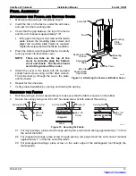
4.
At the switch panel location, use a 2 1/4” hole saw and cut 2 holes 1 1/2” apart.
5. Separate the wires from the relay module into 3 groups:
•
Brown, yellow and gray with spade terminals (interior switch),
•
Black and red with spade terminals (interior power switch),
•
Connector bundle with:
Brown, yellow and gray (exterior switch), and
Blue and white (motor).
NOTE: The relay module harness is supplied with one connector installed. The installer
must furnish the mating connector (p/n 1-480704) and terminals (p/n 350547-3) for the
exterior switch and motor cables. Vendor: AMP/Tyco Electronics.
5/16" Hole
Thru Existing Slots
Top of Channel Routing
Bottom of Channel Routing
E0004
External
Switch Cable
Motor Cable
1 1/2"
Motor Cable
External
Switch Cable
5/16" Hole
Figure 10. Cable Pass Thru Drill Pattern (CS).
Figure 11. Drill Location for Receptacle (SP).
Table of Contents


