background image

Carefree of Colorado Installation 

Manual 

E

CLIPSE

,


OEM 

052547-021 

13 

F

INAL 

A

SSEMBLY


A

TTACHING THE 

F

ASCIA AND 

B

OTTOM 

C

OVER


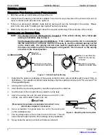
1. 

Make sure the awning is completely closed. 

2. 

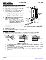
Insert the tab, on the fascia, under the arm base 
and rest it on the mounting plate. 

3. 

Check that the gap between the top of the fascia 
and the arm channel is approximately 1/8". 

  If the gap is too large or too small, set the fascia 

aside, loosen the mounting plate screws and 
adjust the mounting plate height as required.  
Tighten the screws and set the fascia in position. 

4. 

Place the bottom cover beneath fascia.  Carefully 
tuck any wires into the bottom cover. 

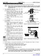
NOTE:  There are tabs on the top of the 

cover to correctly align the bottom 
cover and fascia.  The fascia should 
seat in the groove of the cover. 

5. 

Attach the cover to the fascia with the supplied 
socket head screws using a 9/64” Allen wrench.  
The bolts must go through the cover, the plate, 
and the fascia.  

6. 

Repeat for the other side. 

7. 

Verify proper installation by opening and closing the awning. 

S

ECURING THE 

F

ABRIC


1. 

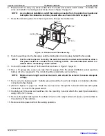
Roll the awning in and out several times to make sure that the fabric is square on the rollbar. 

2. 

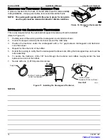
Secure the canopy using one, #6 x 3/8" hex head screw at both sides of the awning. 

Fabric

Alumaguard

1"

#6 x 3/8
Screw

Polyrod

E0014

Fabric

1"

#6 x 3/8
Screw

#6 x 3/8
Screw

Awning Rail

Awning Rail

Awning Rail

Polyrod

Uniguard

Soft Connect


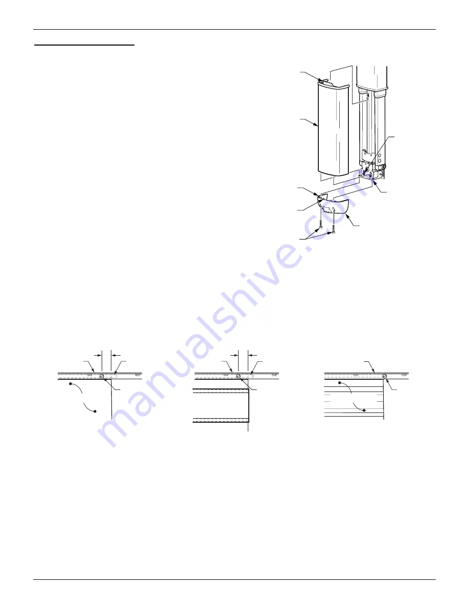
Figure 15.  Securing the Fabric. 

2.1  For vinyl awnings, place screw through awning rail, polyrod and canopy approximately 1” in from 

the end of the fabric. 

2.2  For Uniguard awnings, place screw through awning rail, polyrod and the soft connect material 

approximately 1" in from the end of the fabric. 

2.3  For Alumaguard awnings, place screw on the outer edge of the Alumaguard (not through the 

Alumaguard). 

Facia Tab

Facia

Seat Facia in

Groove

Alignment

Tabs

#8 x 3/4

Socket Head

Cap Screw

Bottom Cover

E0015

Mounting
Plate

Mounting
Plate
Screws


Figure 14.  Attaching the Fascia and Bottom Cover. 

Table of Contents

Summary of Contents for Eclipse XL

Page 1: ...e Patio Awning Specifications 1 Eclipse Patio Awning Options 1 Component Checklist 2 Installation 4 Required Pre Installation Preparation 4 Installing an Awning Rail 4 Assembling the Awning 5 Mounting...

Page 2: ...Y HAZARDOUS SITUATION WHICH IF NOT AVOIDED COULD RESULT IN DEATH OR SERIOUS INJURY AND OR MAJOR PROPERTY DAMAGE CAUTION A CAUTION INDICATES A POTENTIALLY HAZARDOUS SITUATION THAT MAY CAUSE MINOR TO MO...

Page 3: ...ely 40 inches approximately 45 inches Extend Actuation Gas Shock Gas Shock Retract Actuation Motorized roll up Motorized roll up w supplemental spring tension Position Control Motorized roll out in Po...

Page 4: ...rdware Rollbar ordered seperately 2 1 3 15 14 13 12 11 E0012c 10 8 7 5b 5a 6a Arm Assemblies see notes 1 2 24 25 26 29 18 19 6b 9 7 8 7 9 7 Standard XL 4 Electrical Single Switch 18 19 16 17 23 22 20...

Page 5: ...Switch Install 1 5 21 Receptacle Seal Cap 1 22 Spade Connector Female Insulated 2 23 Screw 6 x 1 2 2 24 Relay Module 1 25 Switch DPDT Latching 1 26 Switch DPDT Momentary 1 27 Switch Plate Double 1 28...

Page 6: ...s Flex Connect or the awning arm when in the closed position Standard Awning Rail Mounted to Coach Wall Flex Connect Must Be Flat When the Awning is Closed UNIGUARD E0050 Standard Awning Rail Mounted...

Page 7: ...back of the channel 3 5 Route the excess wire up and out the top of the channel and close the arm 3 6 Secure the top of the arm in the closed position using a plastic wrap or equivalent CAUTION DURING...

Page 8: ...4 1 4 62 1 2 1 4 XL E0022a 90o Typ Centerline of Arm Centerline of Arm Awning Length Fabric Width 5 approx 5 approx Awning Rail Flat Mounting Surface Area 4 1 4 x 70 6 7 Clearance from top of door 6 a...

Page 9: ...using a 5 32 drill bit and a 1 4 x 1 1 2 lag screw 11 Hold the awning closed and carefully remove the plastic wraps at the top of the arms The awning will open a few inches 12 Cap or cover the exposed...

Page 10: ...l the cable and hole using a silicone sealant 2 4 Go to step 4 3 For installations using an external wall mount plug receptacle 3 1 Drill a 15 16 hole through the exterior wall in the location shown i...

Page 11: ...push the wires and switch into the mounting hole then attach the switch plate assembly using four 4 6 x 1 2 screws 12 Restore vehicle power and test the awning operation Wiring Diagram Single Switch...

Page 12: ...h the hole 3 4 Refer to Figure 13 Detail A Insert the terminated wire ends into the back of the receptacle 3 5 Coat the backside of the receptacle flange with silicone sealant and insert the receptacl...

Page 13: ...ng switch The extend retract switch is a double throw momentary contact switch 9 Connect the wires from step 7 to the switches as shown in Figure 13 page 12 10 Run a 12 gauge wire never use less than...

Page 14: ...e Gray Brown Yellow Gray Brown Yellow Detail B Alternate Wire Connection Front View of Switch Panel Rear View of Switch Panel E0032a Carefree of Colorado 6 4 5 1 2 1 2 6 4 5 A 1 2 3 5 6 7 2 1 5 3 7 6...

Page 15: ...ough the cover the plate and the fascia 6 Repeat for the other side 7 Verify proper installation by opening and closing the awning SECURING THE FABRIC 1 Roll the awning in and out several times to mak...

Page 16: ...aguard is extended as shown 2 Unlock the keeper and wrap the tractioner around the roller tube 3 Position the tractioner under the Alumaguard with a 1 4 gap between Alumaguard and tractioner Lock the...

Reviews: