Carefree of Colorado Installation
Manual
E
CLIPSE
,
OEM
052547-021
5
A
SSEMBLING THE
A
WNING
If the installation is using an exterior wall mount plug/receptacle, go to step 4.
CAUTION
T
HE END CAP WITH THE OUTSIDE SWITCH IS SHIPPED ATTACHED TO THE ARM
.
U
SE CARE TO NOT DAMAGE THE
SWITCH
,
ENDCAP OR WIRING DURING INSTALLATION
.
1.
Decide on the location of the switches and control box to determine the cable routing.
2.
If the motor and switch cables are to be routed through the RV wall at the bottom of the arm, no
modification is required. Go to step 4.
3.
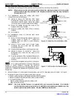
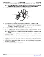
If the motor and switch cables are to be routed through the RV wall at the top of the arm:
3.1 For units with exterior switch: insert the 3-strand cable (switch cable) into the groove in back of
the channel. Allow 5“ of cable to extend from the bottom of the channel. Tie the end cap with
switch to the bottom of the channel to avoid damage during installation.
3.2 Remove the plastic wrap at the top of the motorized arm. Partially open the arm being careful to
not let the arm extend more than 6”.
NOTE: The arm is under tension from the gas shock located in the arm.
3.3
Pull the motor cable out of the hole in the top of the channel.
3.4 For units with exterior switch, insert the switch cable through the hole from the back of the channel.
3.5 Route the excess wire up and out the top of the channel and close the arm.
3.6 Secure the top of the arm in the closed position using a plastic wrap or equivalent.
CAUTION
D
URING ASSEMBLY AND INSTALLATION
,
T
HE ARM ASSEMBLIES MUST REMAIN PERPENDICULAR TO THE ROLLER
ASSEMBLY
.
F
AILURE TO HANDLE THE ARM ASSEMBLIES CAREFULLY CAN BEND THE DRIVE SHAFT
.
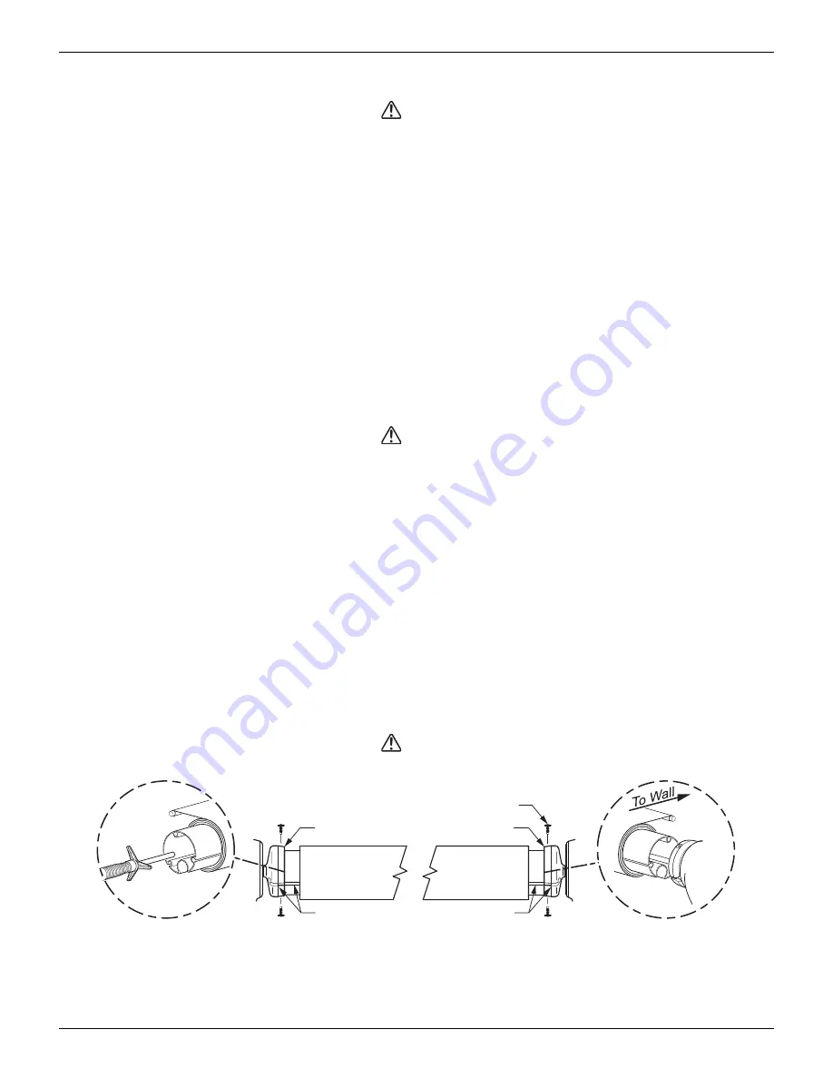
4.
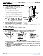
(Refer to Figure 3)
Align the roller assembly with the end cap on the motorized arm assembly. Rotate
the end cap until the slot in the cap aligns with the empty slot in the roller assembly, and then press
the roller assembly fully into the cap. The end cap must seat squarely over the end of the roller
assembly when complete.
NOTE: The roller assembly must be oriented with the fabric going over the roller toward the
mounting surface.
5.
Secure the end cap to the roller assembly using two #10 square-drive screws.
6.
For the standard awning
, repeat steps 4 through 6 to attach the non-motorized arm assembly to the
roller assembly.
7.
For the XL awning
, insert the spring into the roller assy then rotate the end cap until the slot in the cap
aligns with the empty slot in the roller assembly. Finish pressing the roller assembly fully into the cap
and secure using two # 10 square drive screws.
CAUTION
N
O PRE
-
TENSION IS REQUIRED ON THE SPRING
.
Do not
WIND OR TWIST THE SPRING
(XL
ONLY
).
Roller Assembly
Align Slots
End Cap
#10 x 5/8 Screw (qty: 4)
End Cap
E0020
Align Slots
XL ONLY
Figure 3. Assembling the Awning.
Table of Contents


