Carefree of Colorado Installation
Manual
F
REEDOM
RM
P
ATIO
A
WNING
S
WITCH
I
NSTALLATION
(
MOTORIZED AWNINGS ONLY
)
CAUTION
A
LWAYS DISCONNECT THE BATTERY AND ELECTRICAL SOURCES BEFORE WORKING WITH THE ELECTRICAL WIRING
.
1.
Determine the location for the switch.
There is approximately 180cm [70"] of wire from the awning motor. If the distance to the switch
exceeds the furnished wire, the installer must furnish 18 awg wire and butt splice to the motor
wires.
Location should provide the operator a view of the awning during operation.
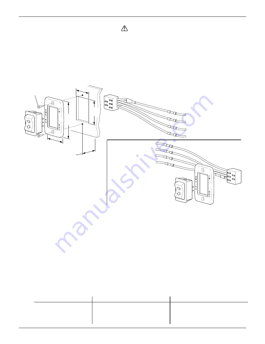
The switch requires a 4.8cm x 7.3cm [1 7/8" x 2 7/8"] area on the mounting surface and a minimum
clearance depth of 3.2cm [1.25'"] from the mounting surface.
1.88”
[4.8cm]
1.25”
[3.2cm]
2.88”
7.3cm
(ref)
1.88”
[4.8cm] (ref)
#6 x 3/4 Screw
(2 plcs)
Black
Red
Blue
White
3.2cm Minimum Clearance
From Mounting Face to
Rear of Switch Connector
- To Chassis Ground
- To BROWN Motor Wire
- To BLUE Motor Wire
- To +12VDC
Black
To Chassis Ground -
To BROWN Motor Wire -
To BLUE Motor Wire -
To +12VDC -
Blue
White
Red
D E T A I L
A
R i g h t S i d e O r i e n t a t i o n
D E T A I L
B
L e f t S i d e O r i e n t a i o n
RMF018
Figure 10. Switch Installation.
2.
Cut a rectangular hole 3.2cm x 4.8cm [1.25" x 1 7/8"] at the location of the switch.
3.
Determine the switch orientation:
The wires of the connector extend from the side of the switch with 3 terminals on the back.
For wire routing on the right side of the switch as shown in Detail A, orient the switch with the 3
terminals on the right.
For wire routing on the left side of the switch as shown in Detail B, orient the switch with the 3
terminals on the left.
Push the switch into the faceplate until the tabs on the switch “click” into place behind the
faceplate. Ensure that the switch and faceplate are oriented so that the lettering is up and the
wires are oriented as desired.
Set switch aside.
4.
Route the awning motor wires through the switch hole and splice to the switch connector:
Connector Wire Color
Right Side Orientation
Left Side Orientation
RED
→
+12VDC
+12VDC
WHITE
→
BLUE
BROWN
BLUE
→
BROWN
BLUE
BLACK
→
Ground
G
ROUND
052978-051r5
8


