background image

Carefree of Colorado Installation 

Manual 

F

REEDOM 

RM


P

ATIO 

A

WNING


052978-051r5 

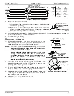
Drill Holes thru Bracket,
Roof & Support Frame

(2 plcs in Front, 2 plcs in Rear of Bracket)

Awning Width

RMF013

L

R

Awning L 

R

 2.5m &  10-11cm 

5-8cm

 3m 

[4”-4.25”] [2”-3”]

 3.5m  10-33cm  5-31cm


[4”-13”] [2”-12”]

 4m 30.5-58cm 23-56cm


[12”-23”] [9”-22”]


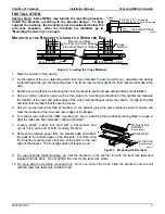
Figure 7.  Mounting the Brackets. 

7.  Position the brackets on the roof. 

RMF013a

Refer to Text for
Suggested Hardware

(4 per bracket)

Support Framing

7.1. The brackets must straddle the frame supports.  Reference the 

marks made previously. 

7.2. Make sure that the outer edges of the brackets are within the 

dimension range shown for the end of the awning.  Adjust the 
bracket and awning position as necessary. 

8.  Drill holes through the brackets, roof and frame as required for the mounting hardware.  Secure the 

brackets with the installer furnished hardware. 

9.  Go to "Mounting the Awning". 

M

OUNTING THE 

A

WNING


1. 

For Motorized Awnings:

  The motor wire comes out of the 

motor endcap under the awning.  Use the dimensions shown to 
locate and drill an 8mm [5/16"] hole into the vehicle. 

NOTE:  Locate the hole to avoid interior framing, cabinets and 

electrical components that could be damaged or 
interfere with the hole location. 

Ensure that the motor wires are accessible after 
routing.  There is 180cm [70"] of wire furnished with 
the motor.  If the final routing to the switch location is 
greater than 180cm, the installer must splice 
additional 18awg wire to the motor wires.   Wire and 
splices are furnished by the installer. 

RMF016

Torque Screw
to 13.6 nm

Mounting Bracket

Awning Frame

M6 x 20 Screw
& Square Nut

(2 per bracket)

5cm - 6.5cm 

[ 2”-2.5”]

8mm 

[ 5/16”] 

Hole

thru Roof

Motorized Only


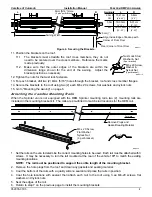
Figure 8.  Mounting the Awning. 


2.  In the rear track of each mounting plate, start twoM6 x 20 

screws and square nuts through the holes in the back of the 
mounting plate.  Do not tighten at this time. 

3. Lift and set the awning into the hooks of the mounting 

brackets.  Pull the case forward to engage the brackets fully. 

4.  Horizontally position the awning on the brackets.  Align the 

inside edge of the RH Endcap with the rear corner of the front 
door (refer to Figure 4 on page 4). 

5.  Tighten the rear screws.  Torque to 13.6 nm. 


Summary of Contents for FREEDOM RM AWNING

Page 1: ...e Brackets Using the Sprinter Rail 3 Attaching the Carefree Mounting Rails 4 Mounting the Brackets On a Flat Roof 5 Mounting the Awning 6 Mount Bottom Brackets 7 Switch Installation motorized awnings...

Page 2: ...r translation of this document in whole or part is strictly prohibited without prior written approval from Carefree of Colorado SAFETY INFORMATION WARNING A WARNING INDICATES A POTENTIALLY HAZARDOUS S...

Page 3: ...s 257 300 350 400 450 500 Widths inches 101 118 138 157 177 197 Extension 200cm 80 250cm 98 LEADING EDGE POSITION ACTUATION AND CONTROL Power Lateral Arm Spring Minimum Tension Open Position Control M...

Page 4: ...Crank Handle Used with Manual Crank Only 1 3 13 Switch Kit Used with Motorized Only 1 4 14 Owner s Manual 1 5 NOTES 1 2 bracket kits are available Kit for applications with a Sprinter rail includes it...

Page 5: ...e sprinter rail measure the location of the inner and outer edges of the cross member flanges inside the vehicle Do this for the first and last cross members that the awning covers 5 Using a non perma...

Page 6: ...using two 2 each M6 x 20 screws flat washers and nylock nuts 15 Go to Mounting the Awning on page 6 Attaching the Carefree Mounting Rails When the Sprinter van is not equipped with the OEM Sprinter m...

Page 7: ...template on the roof and mark the position of the rear edge and the mounting hole locations Connect the marks these will be the installation guidelines For vehicles with tapered sides Use the templat...

Page 8: ...se the dimensions shown to locate and drill an 8mm 5 16 hole into the vehicle NOTE Locate the hole to avoid interior framing cabinets and electrical components that could be damaged or interfere with...

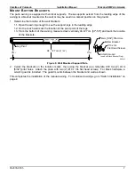
Page 9: ...of the awning measure down vertically 94 127 cm 37 50 and mark the location of the brackets RMF004 94 127 cm 37 50 Bottom Bracket 10 x 3 4 Flat Head Screws Leg Pivot O 4mm 5 32 Pilot Hole Support Legs...

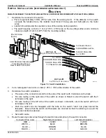
Page 10: ...To Chassis Ground To BROWN Motor Wire To BLUE Motor Wire To 12VDC Blue White Red DETAIL A Right Side Orientation DETAIL B Left Side Orientaion RMF018 Figure 10 Switch Installation 2 Cut a rectangular...

Page 11: ...ded The motor should stop and the fabric should be tight If the motor continues to run the fabric will sag or if the motor quits before the arms are extended it will be necessary to adjust the OUT lim...

Page 12: ...n Manual FREEDOM RM PATIO AWNING BRACKET POSITION TEMPLATE Use this template when mounting brackets without a Sprinter rail 75 2 75 75 Clearance Screw Location Screw Location Clearance Clearance Clear...

Reviews: