Carefree of Colorado
Installation Manual
Mirage
4
052979-003r5
5.
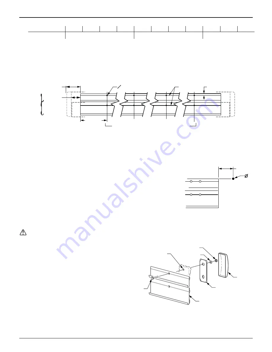
Below is the minimum number of required mounting locations. Each position uses two screws.
Awning Length
12' 13' 14' 15' 16' 17' 18' 19' 20' 21' 22'
# of Locations
4 5
6
6.
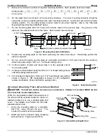
On the plate mark the location of the mounting locations. The inner mounting locations should be
spaced as evenly as possible between the outer mounting locations. Locations must match the frame
location pattern. If a mounting location cannot match a structural member, refer to the "Alternate
Mounting Plate Attachment Method" below.
7.
On the mounting plate drill 7/16” holes at the marks made in the previous step. The grooves in the
plate are the vertical locations for the holes. Each location has two holes.
Grooves
.5" (ref)
MIRAGE004b
O 7/16”
3" (ref)
4 1/2" (ref)
18” Max
(typ)
Hole Pattern to Match Structural Frame
Figure 3. Mounting Plate Hole Drill Pattern.
8.
Position the mounting plate on the coach wall using the marks from step 2. Horizontally position the
plate as required.
9.
On one end of the plate, use the plate as a template and drill an 11/32” pilot hole into the structure.
Attach the plate using a 3/8-16 x 1 1/2 thread cutting screw.
10. Confirm position of plate and repeat step 6 on the opposite end of
the mounting plate.
11. Continue to drill and attach using the 3/8-16 x 1 1/2 thread cutting screws
until all mounting holes are done.
12.
For motorized configurations.
Drill one (1) 1/2” hole through outer wall as
shown in Figure 4. RH configuration is shown, for LH configuration
reverse end location. (Hole is behind the awning motor.)
Alternate Mounting Plate Attachment Method
CAUTION
T
HIS METHOD SHOULD BE USED ONLY AS REQUIRED
.
P
RIMARY ATTACHMENT
MUST
BE INTO
THE STRUCTURE AS DESCRIBED ABOVE
.
When it is not possible to attach into structure or if
the screws will be exposed inside the coach, an
alternate method is to use a backing plate and
cover. The installer must furnish the 3/8 bolts,
washers and lock nuts.
1. Using the mounting plate as a template,
drill 7/16” holes through the wall. The
inside of the wall must be accessible.
2. Attach as shown in Figure 5 using a backing
plate and cover. Torque nuts to 50 in-lb.
3.25"
.5"
MIRAGE005
Figure 4. Cable Routing Hole.
Mounting Plate
3/8 Bolt
Cover
Backing Plate
Washer
3/8 Lock Nut
7/16 Holes
thru Wall
MIRAGE014
Figure 5. Alternate Mounting Method.


