background image

Carefree of Colorado Installation 

Manual 

P

ARAMOUNT


052548-001r11 

I

GNITION 

L

OCKOUT 

S

ENSOR 

I

NSTALLATION 

(O

PTIONAL

Two ignition lockout sensors are available with the Direct Response System. 

  The STD ignition lockout module disables the extend function when the module receives a current 

through a switched 12VDC circuit.. 

  The RTL ignition lockout module will fully retract the awning and disable the extend function when the 

module receives a current through a switched 12VDC circuit.


A switched 12VDC source is a line that is "hot" when the ignition switch is in the on position; or, a 12VDC 
circuit through a relay that is "hot" when a specific condition is met (i.e. releasing the parking brake).  
Relays are not furnished with this kit. 

1.  Disconnect power to the awning.  Shut off the power source or pull the appropriate circuit breaker. 

2.  Locate the control box for the Direct Response System. 

3.  Open the cover of the control box. 

4. 

For Single Awning Applications:


4.1. Disconnect the remote receiver cable from the "EYE" port in the control box.  Do not disconnect the 

cable from the receiver box. 

4.2. Connect the supplied 6" cable to “EYE” port in the control box. 

4.3. Attach the splitter to the other end of the cable. 

4.4. Plug the cable from the remote receiver into the splitter. 

4.5. Attach the Lock-Out Sensor to the end of the 60" cable.  Route the cable as desired and connect 

the cable to the splitter. 

4.6. Proceed to step 6. 

5. 

For Multiple Awning Applications:


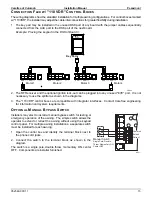
5.1. The module may be connected to the control box as described for single awning applications. 

OR 

5.2. The module may be directly connected to any open "EYE" port on any of the control boards.  It is 

not necessary to use the short cable or splitter. 

5.3. Proceed to step 6. 

NOTE:  

Wires to the module are not pin specific. 

6.  Attach one 18-gauge wire to a terminal of the sensor and route the wire to a suitable 12VDC ground. 

7.  Attach a second 18-gauge wire to the second terminal of the sensor and route the wire to a SWITCHED 

12VDC source. 

8.  Bundle and secure the sensor, cable and wires as required. 

9.  Reattach the control box cover. 

10. Restore power to the awning. 

Summary of Contents for PARAMOUNT

Page 1: ...anical 4 Required Pre Installation Parameters 4 Mounting Plate Layout and Installation 5 Mounting the Awning Unit 5 Installation Electrical 6 Key Pad Installation 6 Control Box Installation 7 Installing the Remote Receiver 8 Ignition Lockout Sensor Installation Optional 9 Wiring Diagram Single Awning 10 Wiring Diagram 2 Awnings 11 Wiring Diagram 4 Awnings 13 Connection Flex w 110VDR Control Boxes ...

Page 2: ...ential personal injury hazards Obey all safety messages that follow this symbol to avoid possible personal injury or death WARNING Indicates a hazardous situation which if not avoided could result in death or serious bodily injury CAUTION Indicates a hazardous situation which if not avoided may result in minor or moderate bodily injury NOTICE Indicates a situation that may result in equipment rela...

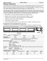
Page 3: ...side walls windows or other accessories the awning can be positioned without concern of obstructions Available for single double and quad installations Lateral support 2 stage arm design 3 pre set extend positions Slide out Cover Slide out Cover Window and full Patio extension PARAMOUNT PATIO AWNING SPECIFICATIONS The following information is for reference only Specific information is detailed in ...

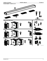
Page 4: ...nstallation Manual PARAMOUNT 052548 001r11 2 COMPONENT CHECKLIST 6 1 2 7 9 20 22 23 24 25 8 5 4 3 10 11 13 12 14 15 18 16 19 17 21 Paramount002 Single Awning Electronics Dual Awning Electronics 4 Awning Electronics ON OFF 26 ...

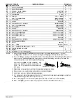
Page 5: ... Lighting A R 8 Notes 1 Awning configuration is specified at time of order including awning length LH or RH configuration fabric color etc Check awning assembly against original purchase order 2 Quantity of 4 per awning is standard for item 2 mounting brackets Some Original Equipment Manufacturer OEM installations may specify a different quantity Mounting brackets are ordered separately and not in...

Page 6: ...rcuit for the awning system that is protected by an appropriate sized fuse circuit breaker Each patio awning draws a maximum of 3 amps The motion sensor for the Direct Response system is mounted on the patio awning 10 feet cable is available from the awning wall mount and will require a routing path to the control box If the control box is located at a distance greater than 10 feet the installer m...

Page 7: ...e in back of mounting plate Do not tighten at this time 7 At the motor location drill one 1 1 2 hole through outer surface The position may be under or behind the awning position MOUNTING THE AWNING UNIT CAUTION The Apex awning is extremely heavy Moving and or lifting the awning requires a minimum of 3 people The use of a lifting device is strongly recommended 1 While lifting the awning route the ...

Page 8: ...e is available from the awning wall mount and will require a routing path to the control box If the control box is located at a distance greater than 10 feet the installer must provide a terminated jumper cable from the box location to the cable end Terminated cable is a 4 wire RJ11 terminated phone cord straight no twist NOTE Cable lengths of the furnished cables are listed in the chart with the ...

Page 9: ... 4 screws each The screws must be mounted in opposite corners 3 Route a 2 conductor 14AWG NM wire with ground from the AC power source to the box It is recommended that the installer provide a dedicated AC circuit that is protected by an appropriate sized fuse circuit breaker Each patio awning draws a maximum of 3 amps NOTE Each board must have a 110VAC supply The diagram shows a separate power so...

Page 10: ...on on the remote The red light will go out after the receiver learns the remote signal CAUTION When the receiver learns the transmitter signal the system will perform the operation of the button pressed Example Pressing an Extend button during the learning phase will cause the awning to extend when the receiver learns the signal Use caution to avoid unexpected movement by the awning 4 Repeat steps...

Page 11: ...ions 4 1 Disconnect the remote receiver cable from the EYE port in the control box Do not disconnect the cable from the receiver box 4 2 Connect the supplied 6 cable to EYE port in the control box 4 3 Attach the splitter to the other end of the cable 4 4 Plug the cable from the remote receiver into the splitter 4 5 Attach the Lock Out Sensor to the end of the 60 cable Route the cable as desired an...

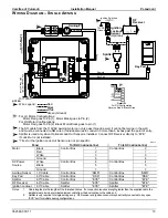
Page 12: ...wning configurations TO EYE PORT on RP24 Program Mode Press to Learn Transmitter UP RF Receiver GRN BLK WHT RED Key Pad DR013 Ignition Switched 12VDC 12VDC Ground Ignition Lockout Sensor Optional Splitter Sensor Key Pad Awning 1 3 5 4 2 Conductor 14AWG NM Wire w Gnd To 110VAC AMD SUN AUX EYE DSK BLK WHT RED GRN grn wht blk 1 7 6 5 4 3 2 1 7 6 5 4 3 2 3 Conductor 14AWG NM Wire w Gnd Sensor Remote R...

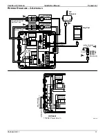
Page 13: ...12VDC Ground Ignition Lockout Sensor Optional Sensor 1 Key Pad Sensor 2 Awning 1 3 5 RED WHT BLK GRN BLK WHT RED GRN Wht Blk Grn Wht Blk Grn 2 Conductor 14AWG NM Wire w Gnd To 110VAC AMD SUN AUX EYE DSK AMD SUN AUX EYE DSK 1 7 6 5 4 3 2 1 7 6 5 4 3 2 1 7 6 5 4 3 2 3 Conductor 14AWG NM Wire w Gnd Sensor GRN BLK WHT RED Awning 2 Sensor Remote 3 3 Conductor 14AWG NM Wire w Gnd DETAIL A 110VAC Power L...

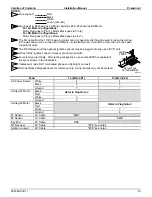
Page 14: ...to Pin 2 For RH Motor Configurations Motor Red goes to Pin 2 Motor Black goes to pin 1 3 The SO cable from the 110VAC awning motor can only pass directly through a wall it cannot be laid up in the wall and must be connected to NM wire or individual wires in conduit no more than 6 inches past the point of entry NOTES 4 DR016a 5 Wires for the Ignition Lock Out Sensor are not pin specific The RF Reci...

Page 15: ...RN AMD SUN AUX EYE DSK AMD SUN AUX EYE DSK AMD SUN AUX EYE DSK AMD SUN AUX EYE DSK 1 7 6 5 4 3 2 1 7 6 5 4 3 2 1 7 6 5 4 3 2 1 7 6 5 4 3 2 1 7 6 5 4 3 2 To 110VAC 3 Conductor 14AWG NM Wire w Gnd To 110VAC Sensor GRN BLK WHT RED Awning 2 Sensor Remote 3 3 Conductor 14AWG NM Wire w Gnd GRN BLK WHT RED Sensor 3 Sensor 4 Awning 3 3 3 Conductor 14AWG NM Wire w Gnd Sensor GRN BLK WHT RED Awning 4 Sensor...

Page 16: ...le the installer must provide a terminated jumper cable from the box location to the cable end Green Ground White Red Black 1 Wire Legend 2 Awnings 1 4 shown as LH Motor Awnings 2 3 shown as RH Motor For LH Motor Configurations Motor Red goes to Pin 1 Motor Black goes to Pin 2 For RH Motor Configurations Motor Red goes to Pin 2 Motor Black goes to pin 1 3 The SO cable from the 110VAC awning motor ...

Page 17: ...l boxes are compatible with integrator interfaces Contact Carefree engineering for information and system requirements OPTIONAL MANUAL BYPASS SWITCH Installers may elect to install a manual bypass switch for testing or emergency operation of the awning The simple switch allows the operator to extend or retract the awning without using the keypad control panel For multiple awning installations a se...

Page 18: ... disconnects NOTE Allow adequate slack in the 12VDC power line so that the in line fuse installed in step 4 can be accessed from behind the switch 5 Install the in line fuse 5 1 Near the switch cut the red 12VDC power line to the switch Do not strip the insulation 5 2 Insert a wire end into one of the wire channels until it butts up against the stop 5 3 Fold that half of the connector body over un...

Page 19: ...again The awning should stop 3 4 Press the extend button a third time Observe the awning it should fully extend The system performs an auto tension action when the awning is fully extended The awning rolls in reverse to tension the fabric The auto tension feature works only with the extend function when the awning is fully extended 4 Check the retract function 4 1 Press the Awning 1 RETRACT button...

Page 20: ...at the intermediate positions 6 For multiple awning installations it is recommended that all awnings be calibrated at the same time while operating on the same power source i e do not calibrate one awning while operating on the inverter and another while operating on the generator 7 If a calibration is started and fails stops for any reason the system resets the travel time and maximum run time to...

Page 21: ... be reinitialized to continue Any awnings that were stopped partially through a calibration will be reset to the default values In calibration mode any or all awnings can be calibrated and or re calibrated 4 At the keypad or on the remote press and release the Patio button to start the calibration for the selected awning The awning will partially extend then retract to determine the full retract p...

Page 22: ...justment is correct 3 4 Repeat the procedure until the awning extends correctly 4 If the arms do not extend completely 4 1 Retract the awning approximately 10 12 4 2 Using a 4mm Allen wrench turn the OUT limit switch CLOCKWISE to increase the time the motor runs 4 3 Extend to confirm that the adjustment is correct 4 4 Repeat the procedure until the awning extends correctly Adjusting the IN Limit S...

Page 23: ...l the lead rail matches the adjacent awning lead rail Tip If the screw is hard to turn have a second person lift up on the lead rail then turn the screw and let the lead rail down Repeat until the lead rail is at the desired height 5 Tighten the securing screws 30 33 ft lbs MANUAL OVERRIDE If 110V power is not available to the coach the Paramount awning can still be safely retracted using the manu...

Reviews: