Carefree of Colorado Installation
Manual
T
RAVEL
'
R
052540-002r4
7
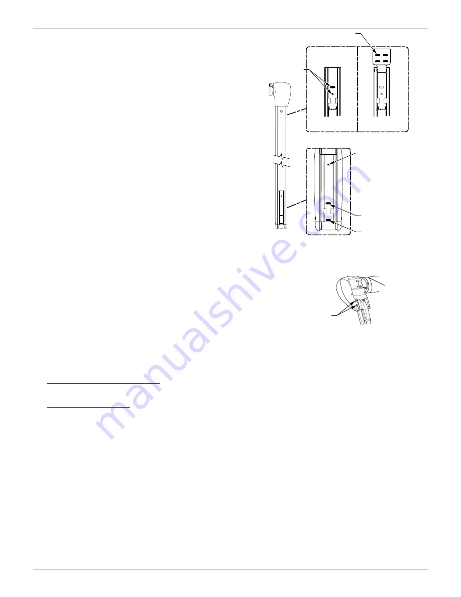
8. Confirm that the arm is perpendicular to the
awning rail, attach the arm through the #1
mounting hole (shown in Figure 8) using a 5/32”
pilot hole and a 1/4 x 1-1/2” lag screw.
9. Position the roller assembly so that it is
perpendicular to the motorized arm assembly.
Position the non-motorized arm perpendicular to
the roller assembly.
10. Drill a 5/32” hole through the #2
mounting hole
and attach the non-motorized arm using a 1/4 x
1 1/2” lag screw.
11. Check the alignment; the arm assembly must be
perpendicular to the roller assembly. When the
alignment is correct, drill and attach the arm
through the #1 mounting hole (shown in Figure
8) using a 5/32” drill bit and a 1/4 x 1-1/2” lag
screw.
12. Hold the awning closed and carefully remove the
plastic wraps at the top of the arms. The awning
will open a few inches.
13. Open the awning about 18” or until the top
mounting holes on the arms are visible. To open
13.1
Cap the exposed end of the wires from the motor cable to
avoid grounding or shorting. These must remain capped
and detached from the switch when using the emergency
terminals.
13.1
Attach the supplied jumper cables to the emergency terminals
located on the back of the motorized head.
13.2 Connect the other ends of the jumper leads to a 12V
source (i.e. drill battery). If the awning does not begin to
move, reverse the leads.
14. Drill 5/32" pilot holes for the upper mounting holes and the #3 lower mounting hole for each arm.
15.
For Aftermarket configurations:
Attach the upper mounting bracket using 2 ea 1/4 x 2 1/2 lag screws.
Attach the #3 lower mounting hole with a 1/4 x 1 1/2 lag screw or moly rivet.
16.
For OEM configurations:
Attach the upper mounting holes using 2 ea 1/4 x 1 1/2 lag screws. Attach the
#3 lower mounting hole with a 1/4 x 1 1/2 lag screw or moly rivet.
Upper Mounting Holes
(Arm Extended Out)
Lower Mounting Holes
#1
Mounting Hole
#2
Mounting Hole
OEM Mounting Holes
1/4 x 1 1/2 Screws Only
TravelR005
#3
Mounting Hole
OEM
Configuration
Aftermarket
Configuration
Aftermarket Mounting Holes
1/4 x 2 1/2 Screws Only
For #1, 2 and 3 use
1/4 x 1 1/2 Screws
or
3/16 Moly Rivets
Figure 8. Arm Mounting Hole Locations.
TravelR010c
Emergency
Terminals
RH Motor Head
Figure 9. Emergency Terminals.


