background image

052540-002r14 

Printed in USA 

September, 2018 


I

NSTALLATION 

M

ANUAL


T

RAVEL

'

A

RMS AND 

C

ANOPY

T

HIS MANUAL PROVIDES INSTRUCTIONS FOR

O

RIGINAL 

E

QUIPMENT 

M

ANUFACTURER 

(OEM),


A

FTERMARKET 

I

NSTALLATIONS AND 

ARM UPGRADES FOR CURRENT 

C

AREFREE AND 

A&E


A

WNINGS

RV


Read this manual before installing or using this product.  Failure to follow the instructions 
and safety precautions in this manual can result in personal injury and/or cause the 
product to not operate properly. 


T

ABLE OF 

C

ONTENTS


Product Overview .......................................................................................................................... 1


Component Checklist.............................................................................................................................. 2


Installation ..................................................................................................................................... 3


Required Pre-Installation Preparation ..................................................................................................... 3


Installing an Awning Rail ......................................................................................................................... 4


Assembling the Awning .......................................................................................................................... 5


Mounting the Awning .............................................................................................................................. 6


Switch and Wiring Installation ................................................................................................................. 8


Wiring Routing ........................................................................................................................................ 8


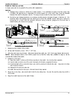
Single Switch Installation ........................................................................................................................ 9


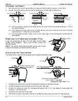
Securing the Fabric ............................................................................................................................... 10


Removing the Temporary Assembly Pins ............................................................................................. 10


Installing the Tractioners ....................................................................................................................... 10


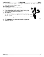
Attaching the Fascia ............................................................................................................................. 11


Optional LED’s ............................................................................................................................. 12


Wire Routing ......................................................................................................................................... 12


Switch Installation ................................................................................................................................. 13


Power Connection for optional OEM RGB LED's ................................................................................. 14


Summary of Contents for TRAVEL'R

Page 1: ...anual can result in personal injury and or cause the product to not operate properly TABLE OF CONTENTS Product Overview 1 Component Checklist 2 Installation 3 Required Pre Installation Preparation 3 Installing an Awning Rail 4 Assembling the Awning 5 Mounting the Awning 6 Switch and Wiring Installation 8 Wiring Routing 8 Single Switch Installation 9 Securing the Fabric 10 Removing the Temporary As...

Page 2: ... follow this symbol to avoid possible personal injury or death WARNING Indicates a hazardous situation which if not avoided could result in death or serious bodily injury CAUTION Indicates a hazardous situation which if not avoided may result in minor or moderate bodily injury NOTICE Indicates a situation that may result in equipment related damage General Safety WARNING Shock Hazard Always discon...

Page 3: ...es Measurement is from centerline of Awning Rail to centerline of roller tube MOTOR Power 10VDC 14VDC Circuit Rating 15 amp motor mounted in arm POWER SOURCE Motor and controls are routed and hardwired into the vehicle s 12V system EXTEND ACTUATION Gas Shock POSITION CONTROL Motorized roll out in CONTROLLER 3 position momentary ON center OFF Switch COLOR Frame White Black Canopy Available in a Var...

Page 4: ...10 2 15 Switch Kit Note 1 4 16 Jumper Cable 1 1 3 Notes 1 Awning configuration is specified at time of order including awning length fabric color etc Check awning assembly against original purchase order Arms are configuration specific and are not interchangeable 2 Screws and Tractioners are furnished with roller tube assemblies equipped with optional Alumaguard 3 Place Jumper Cable item 16 and Ow...

Page 5: ... C Auto Retract All Disconnect and remove the existing control boxes wiring and switches The system is replaced with the single switch control Travel r Direct Response Auto Retract is available as a separate upgrade kit SR0093 for the Travel r Patio Awning 3 3 Remove the awning from the coach including the roll bar and canopy 3 4 Remove all brackets 3 5 Plug and seal all mounting holes The new arm...

Page 6: ...the door frame or light fixtures The centerline of the awning rail should be above the door opening a minimum of 6 for vinyl and 7 for Alumaguard Uniguard After determining mounting position mark the position with a chalk line 2 Awning rail must be level 3 Seal the back of the rail with silicone sealant or putty tape 4 Align the awning rail onto the wall and secure with 10 x 3 4 screws Use all the...

Page 7: ... the top of the channel 3 3 Close the arm 3 4 Secure the top of the arm in the closed position using a plastic wrap or equivalent 4 For Aftermarket and Upgrade Installations On each arm attach the top mounting bracket to the channel using the screw and nut and as shown 5 Align the roller assembly with the end cap on the motorized arm assembly Rotate the end cap until the slot in the cap aligns wit...

Page 8: ... of the motorized arm with the centerline marked in step 2 Butt the top of the rear channel against the awning rail as shown IMPORTANT NOTE For Uniguard and Alumaguard installations the centerline of the roll bar must be 3 4 1 4 above the centerline of the awning rail If the arm cannot be positioned as shown and meet this requirement because of trim below the awning rail the installer must remove ...

Page 9: ...mounting holes on the arms are visible To open 12 1 Temporarily connect the ends of the motor wires to a 12V 14V source i e drill battery If the awning does not begin to move reverse the leads 12 2 Remove the battery after the awning is open 13 For Aftermarket configurations Drill 5 32 pilot holes for the upper mounting holes through the bracket and the 3 lower mounting hole for each arm Then atta...

Page 10: ...r cable and switch location 2 FOR ONE TOUCH UPGRADES 2 1 If the external wall plug has been removed and sealed go to step 3 2 2 If using the wall plug measure the motor cable from the arm to the plug Trim the wire and terminate with an installer furnished mating connector Attach the new connector to the wall plug and proceed to step 12 3 For installations using the cable with a direct connection t...

Page 11: ...r wire BLACK motor wire BLUE BLACK motor wire RED motor wire BLACK Ground Ground 5 Run a minimum 14 awg wire from the power distribution panel auxiliary battery circuit or equivalent The circuit should be protected by a 15 amp fuse 6 Run a minimum 14 awg wire to system ground NOTE If the wire run is 30 feet or longer use 12awg wire to prevent voltage drop 4 Route the two wires through the mounting...

Page 12: ...will temporarily operate with the pins in place however for long term use the pins must be removed INSTALLING THE TRACTIONERS The tractioners are used with the Alumaguard and Uniguard metal fabric wraps 1 Partially extend the awning until the Alumaguard Uniguard is extended as shown 2 Unlock the keeper and wrap the tractioner around the roller tube 3 Position the tractioner under the Alumaguard Un...

Page 13: ... close the awning 2 On the outer channels use a non permanent method of marking and mark the bottom of the inner channel Repeat for both arms 3 Open the awning 4 From behind slip the fascia between the outer channels of the lower arm Align the mounting dimples of the fascia with the mounting slots in the outer channels 5 The fascia should sit approximately 1 8 below the marks made in step 2 6 Pres...

Page 14: ...between the canopy and rear channel 1 3 Secure the LED harness inside the channel with a quality silicone sealant 2 For optional OEM awning rail LED s 2 1 Route the LED power harness into the vehicle with the awning motor wires Allow 3 4 to extend past the top of the channel 2 2 For white LED s On the outside of the vehicle connect the power cord to the LED strip LED001a Attach Wires Along Bottom ...

Page 15: ...Allow adequate slack in the 12VDC power line so that the in line fuse installed in step 4 can be accessed from behind the switch 4 Install the in line fuse 4 1 Near the switch cut the red 12VDC power line to the switch Do not strip the insulation 4 2 Insert a wire end into one of the wire channels until it butts up against the stop 4 3 Fold that half of the connector body over until the element co...

Page 16: ...he awning 2 Route the Red wire to 12Vdc 3 Route the Black wire to ground 4 Ensure that the connections are tight solid and sealed when completed 5 For awning rail applications 5 1 Mount the control module and RF sensor on the outside of the vehicle as shown using double sided tape 5 2 Connect the module wires to the power harness and LED strip NOTE The LED connector and receiver connectors must be...

Reviews: