22
ENG
+0300046IE - rel. 1.2 - 14.01.2021
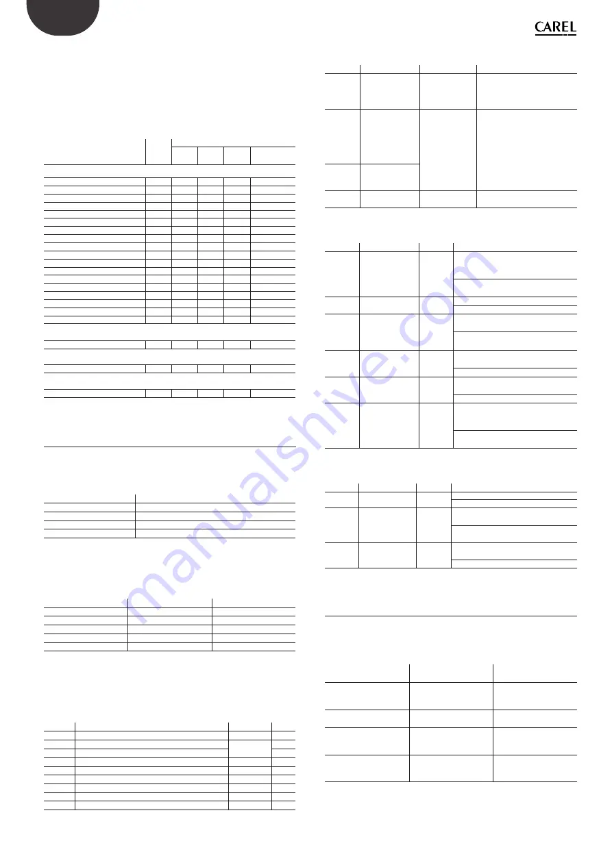
Response time
The response time T50 or T90 (in seconds) is the time taken to reach 50%
or 90% respectively after supplying the target gas at a concentration of
100% of the sensor’s full scale.
T10 is the time needed to return from 100% to 10% of the sensor’s full
scale. Response times are typical values measured under reference
conditions. All response times are expressed in seconds and represent
nominal values.
Type of gas
Range
[ppm]
Average response time [s]
T50
T90
T100
T10
(return)
Semiconductor, refrigerant
HFO1234YF
1000
132
348
544
300
HFO1234ZE
1000
154
429
903
363
R134A
1000
240
597
860
612
R32
1000
72
222
473
200
R404A
1000
104
315
495
248
R407A
1000
94
391
676
420
R407F
1000
114
412
732
366
R410A
1000
67
247
483
217
R448A
1000
95
307
544
233
R449A
1000
110
339
552
291
R450A
1000
158
494
844
462
R452A
1000
98
340
601
268
R452B
1000
86
265
539
281
R454A
1000
98
293
592
251
R507
1000
72
238
486
223
R513A
1000
135
411
659
452
R454B
1000
71
223
595
294
R455A
1000
97
262
598
309
NDIR
CO2
10000
28
140
366
150
Electrochemical
(NH3)
100
22
101
413
97
Semiconductor, flammable
R290
2500
10
22
98
36
Tab. 5.g
5.4 Modbus registers
5.4.1 Modbus connections
The RS485 port allows communication with the gas detector using the
Modbus-RTU protocol.
Connection symbol
Meaning
B
-, Rx, inverting signal
A
+, Tx, non-inverting signal
GND
Earth reference (other than 0 V)
SH
Shielded cable connection
Tab. 5.h
5.4.2 Modbus configuration
The RS485 communication settings can be selected.
Setting
Selection
Default
Address
1 to 247
1
Baud rate
9600 -19200 baud
19200 baud
Stop bits
1-2
2
Parity
None-Odd-Even
None
120 Ω termination
Enable-Disable
Disable
Tab. 5.i
5.4.3 List of variables
04 - Input Registers - R
Register Description
Range
Unit
100
Gas concentration level (% of full scale)
0 : 100
%
101
Gas concentration level in ppm
See the gas
range table
ppm
103
Full scale sensor level in ppm
ppm
104
Low alarm set point (% full scale) (local)
0 : 100
%
105
Sensor timer
0 : 65,535
hours
106
Detector Modbus address
1 : 247
107
Software version (firmware revision)
-
108
Machine code (proprietary machine number)
527
109
Order number
300
Tab. 5.j
03 - Holding Registers - R/W
Register
Description
Range
Details
200
High alarm
set point (ppm)
See the
gas range table
High alarm set point / thresh-
old in parts per million (set
by controller, overwrite local
sensor values)
201
Alarm delay
0 : 15
Buzzer-alarm delay sets the
time (in minutes) that the
buzzer flag and alarm flag are
activated after the gas con-
centration exceeds the alarm
set point.
202
Buzzer delay
(mapped to
register 201)
The values set for reg. 201 and
reg. 202 are always the same
203
Low alarm alarm
set point (ppm)
See the gas range
table
Low alarm set point / threshold
level in parts per million
Tab. 5.k
02 - Input Status - R
Register Description
Range
Details
300
High alarm flag
0 : 1
1: The gas concentration is greater
than or equal to the high alarm set
point
0: The gas concentration is below the
high alarm set point
301
Relay status
0 : 1
1: One or more relays are active.
0: All relays are inactive
302
Sensor fault
0 : 1
1: Sensor not found or sensor open
circuit detected.
0: Sensor found in the circuit and no
open circuit fault detected
303
Red LED
0 : 1
1: The red LED is on. Alarm/fault
indication.
0: The red LED is off.
304
Green LED
0 : 1
1: The green LED is on.
Warm-up status or normal operation.
0: The green LED is off.
307
Low alarm flag
0 : 1
1: The gas concentration is greater
than or equal to the low alarm set
point
0: The gas concentration is below the
low alarm set point
Tab. 5.l
01 - Coils Status - R/W
Register Description
Range
Details
400
Buzzer flag
0 : 1
1: buzzer on
0: buzzer off
401
Test flag
0 : 1
1: Sensor on/operating for more than 1
year and requires testing.
0: The sensor does not yet require
testing.
402
Relay contact
behaviour
0 : 1
1: Fault relay operation (see the relay
logic table)
0: Standard relay operation (default)
Tab. 5.m
4.1 Relay logic table
Relay behaviour with relay failsafe operation (register 402)
0: Standard relay operation (default)
1: Relay failsafe operation
This register value will affect each relay.
Event cause
0: Standard operation
(default)
1: Failsafe operation
At power on
Relays 1, 2, 3 de-ener-
gised:
NO the output is open
Relays 1, 2, 3 energised:
NO the output is closed
Sensor fault active
Relay 3 energised:
NO the output is closed
Relay 3 de-energised:
NO the output is open
If the gas level exceeds
the low alarm threshold
register 203
Relay 2 energised:
NO the output is closed
Relay 2 de-energised:
NO the output is open
If the gas level exceeds
the high alarm threshold
register 200
Relay 1 energised:
NO the output is closed
Relay 1 de-energised:
NO the output is open
Tab. 5.n
Summary of Contents for GDWB
Page 2: ......
Page 4: ...4 ITA 0300046IE rel 1 2 14 01 2021...
Page 6: ......
Page 26: ...26 ITA 0300046IE rel 1 2 14 01 2021 Notes...
Page 28: ...4 ENG 0300046IE rel 1 2 14 01 2021...
Page 30: ......
Page 50: ...26 ENG 0300046IE rel 1 2 14 01 2021 Notes...
Page 51: ......


