background image

22

ENG

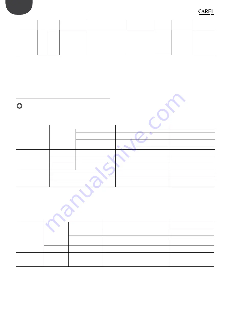
“Ultrasound for fancoil” +0300059IE - rel. 1.5 - 15.07.2019

red LED signal 

(*)

code and 

symbol on di-

splay (fl ashing)

meaning

cause

solution

alarm relay 

activation

action

reset

9 fast fl ashes

EtL

End of piezoelectric 
transducer life

The unit has reached AF 
working hours (default 9999 h)

Replace the 
piezoelectric 
transducers to 
guarantee rated unit 
production

yes

signal only

Reset internal 
piezoelectric 
transducer coun-
ter by setting 
parameter d6 to 
zero (See chapter 
5.8)

Tab. 8.a 

To reset the alarms, press ESC once to mute the buzzer, press ESC a 
second time to completely reset the alarm.

(*) Fast fl ash: 0.2 seconds  ON and 0.2 seconds OFF
     Slow fl ash: 1 second ON and 1 second OFF

8.1 Troubleshooting

Note:

 if the problem identifi  ed cannot be solved using the following

guide, contact CAREL technical service.

1. 

Firstly, check the humidifi  er and the surrounding area.

Problem

Cause

Check

Solution

No atomised water
production

Power supply

Terminal M14 open

Visual verify

Connetct 

terminal M14 to a  bridge

No power

Measure the voltage at the humidifi er
input terminals of the transformer

Connect power

Power supply fault

Measure the voltage at the power 
supply output terminals

Replace the power supply

Feedwater system

Valve closed upstream

Check

Open the valve

The quantity of atomised
water is too low

Power supply

Low power supply voltage

Check the voltage at the power supply
output terminals

Replace the power supply, if
damaged

Feedwater system

Water level during production
is too high and overfl  owing

Check visually

See table 2)

Other

The humidifi  er is not installed
horizontally

Check visually

Adjust

No atomised water 
production

Dust and foreign matter accumulated in the tank (*)

Clean the inside of the tank

Transducer deterioration

Verify the d6 >0 parameter

Repalce if d6=0

The quantity of atomised
water is too low

Dust and foreign matter accumulated in the tank (*)

Check a view the inside of the tank

Scale build-up on the surface of the piezoelectric 
transducers (*)

Clean the inside of the tank
and replace the transducers

Tab. 8.b 

(*) These malfunctions can be avoided by carrying out preventive
maintenance.

2. 

If the cause has not been identifi  ed with the previous checks, there 
may be faulty components. Check the inside of the humidifi er.

Problem

Cause

Check

Solution

No atomised water
production

Feedwater system Float level sensor fault

Empty the tank, remove the electronic board
and check continuity of the level sensor

Contact service to replace the level 
sensor

Float level sensor blocked

Clean the sensor. If normal opera-
tion is not restored, replace

Fill valve fault

No water fi  lled even when the tank has been 
emptied

Replace the valve
Clean the sensor. If normal opera-
tion is not restored, replace

Other

The fan cables are loose or
detached

Check connection after removing the
humidifi er cover

Restore correct connection to the 
terminals

The quantity of 
atomised
water is too low

Water level over-
fl ow

Float level sensor blocked

If the water level in the tank reaches the overfl ow 
pipe, remove the connector from the control board 
and check continuity of the level sensor

If there is continuity, contact service 
to replace the level sensor

Fill valve fault

Water is fi  lled even after switching off  the appliance Replace the fi  ll valve

Tab. 8.c 

Summary of Contents for humiSonic UU01F

Page 1: ... S o l u t i o n s NO POWER SIGNAL CABLES TOGETHER READ CAREFULLY IN THE TEXT LEIA Y GUARDE ESTAS INSTRUÇÕES READ AND SAVE THESE INSTRUCTIONS Manual de utilização POR Umidificadores de ultrassons User manual Ultrasound humidifier ...

Page 2: ......

Page 3: ...vistas sanções estabelecidas pelas normativas locais vigentes em matéria de eliminação _________________________________________________________________ GARANTIA SOBRE OS MATERIAIS 2 anos a partir da data de produção excluindo as partes de consumo HOMOLOGAÇÕES aqualidadeeasegurançadosprodutosCARELsãogarantidasnãoapenaspelosistemade projetação e produção certificado ISO 9001 como também pela marca ...

Page 4: ......

Page 5: ...or a partir do visor 16 7 PARÂMETROS DE CONFIGURAÇÃO 17 7 1 Parâmetros de base 17 7 2 Parâmetros avançados 17 7 3 Parâmetros de conexão serial 20 7 4 Parâmetros de só leitura 21 8 ALLARMI 21 8 1 Resolução dos problemas 22 9 MANUTENÇÃO E PEÇAS DE REPOSIÇÃO 23 9 1 Peças de reposição 23 9 2 Limpeza e manutenção do tanque 23 9 3 Limpoeza e manutenção de outros componentes 23 10 ESQUEMAS ELÉTRICOS 24 1...

Page 6: ...Fig 1 Conteúdo da embalagem versão 230 Vca Atenção antes de proceder com a montagem remova o depósito do suporte empurrando nas aletas pretas como indicado na figura Nota na versão 115 Vca em lugar do transformador E são fornecidos os 2 transformadores E1 115 50 Vca e E2 115 24Vca ...

Page 7: ...ndo a embalagem pela parte de baixo abra a caixa de papelão retire os separadores de material anticolisão e retire o umidificador O conteúdo é constituído por fig 1 A fixação B depósito C eletroválvula de carga D eletroválvula de descarga E transformador controle se a tensão está correta para a versão 110V o transformador 24V está separado do transformador 50V F kit de cabos há dois pares de cabos de...

Page 8: ...do transformador C Drain Fill 24Vac 50Vac Drivers A B C Fig 1 f 4 Conecte os cabos de alimentação e controle à s placa s condutoras posicionadas no fundo do depósito segundo a figura veja serigrafia nos cabos LIGAÇÕES FICHA DEPÓSITO CONECTOR JST 8 VIAS 50 1 6 50 2 7 50 2 3 C 2 8 50 1 2 C 1 4 Fig 1 g 5 Segure o recipiente B com as duas mãos 6 introduza o recipiente verticalmente na estrutura de fixaçã...

Page 9: ... válvula de carga 2 1 Água de alimentação O umidificador de ultrassom funciona com água desmineralizada Se utilizar a água normal isso irá diminuir a vida dos transdutores e em especial o intervalo de manutenção para limpeza ou substituição dos transdutores é muito menor tanto quanto a água contém sais minerais superiores ao recomendado na tabela 11 b pág 24 água de alimentação No caso de utilizaçã...

Page 10: ...10cm a adição de curvas e estrangulamentos pode causar condensação e diminuir a quantidade de umidade imitida evite solicitações que comportem estresse mecânico no terminal de saída da umidade Fig 3 a Fig 3 b 3 2 Ducto para ventilador Fig 3 c O ducto UUKCY00000 pode ser instalado na parte superior do ventilador removendo a grelha de proteção de modo a tomar o ar de um sítio diferente daquele onde ...

Page 11: ...os vazamentos de carga Se na instalação for utilizado o sistema de distribuição UUKDP0 00 rode o tubo até os furos ficarem na direção do fluxo de ar veja figura Fig 3 i Atenção a união dos tubos em relação à entrada de ar no humiSonic e ao envio da água nebulizada no ducto tem de ser posicionada de modo a evitar as diferenças de pressões Um excessivo desequilíbrio das pressões poderia causare uma ano...

Page 12: ...egundo o quanto exigido pelas normas vigentes CEI EN 60335 1 Antes de proceder à realização das conexões assegure se de que a máquina esteja secionada pela rede elétrica Verifique se a tensão de alimentação do aparelho corresponde ao valor indicado nos dados de matrícula presentes na parte lateral do produto Conecte o cabo de alimentação de saída do transformador à placa eletrônica Placa de bornes ...

Page 13: ...a placa base conecte os bornes M10 1 e M10 2 a um umidóstato ou contato remoto contato limpo Defina o parâmetro A0 0 para habilitar a ação On Off veja cap 7 REGULADOR PROPORCIONAL EXTERNO ação modulante jumpeie o borne M14 1 e M14 2 habilitação na placa base conecte os bornes M10 1 e M10 2 pedido de produção a um regulador externo defina o parâmetro A0 1 para ativar a ação modulante veja cap 7 e o pa...

Page 14: ...essivo às horas de inatividade contínuas definidas em b2 5 ARRANQUE INTERFACE COM O USUÁRIO E FUNÇÕES DE BASE Antes de ligar o umidificador verifique ligações hidráulicas cap 2 em caso de vazamentos de água não ligue o umidificador antes de resolver o problema distribuição do vapor cap 3 e conexões elétricas cap 4 5 1 Arranque 1 O umidificador uma vez alimentado e com o consenso habilitado on off remoto...

Page 15: ...Alarme LED vermelho Com a ativação de um alarme led intermitente e besouro ativo Se alarme estiver ativo premindo ESC o besouro se apaga e o LED fica fixo uma ulterior pressão da tecla ESC reinicializa os alarmes veja cap 8 Tempo em segundos Contador de horas Produção percentual de umidade relativamente à capacidade nominal Modificação em curso dos parâmetros setup dos parâmetros Pedido de manutenção...

Page 16: ... cabo de conexão Se o problema persistir contate a assistência Para modificar o parâmetro visualizado prima ENTER visor UP ou DOWN para modif o valor ENTER para confirmar o novo valor Pressione ESC para regressar à máscara principal É possível acessar os parâmetros também a partir da lista dos parâmetros veja cap 7 6 5 Visualização de atualização de Software 1 quando se liga a máquina no visor apare...

Page 17: ... a aprtir de TAM s 0 60 2 bA Tempo máximo de carga min 0 30 2 bb Tempo de reposição da água na produção s 0 120 5 bC Tempo máximo de descarga s 0 1500 60 bd Tempo de abertura da descarga para esvaziamento completo do tanque s 0 1500 30 bE Tempo de atraso a partir do registro do baixo nível para reposição s 1 20 10 bF Atraso na ativação da descarga em stand by se a eletroválvula de descarga estiver...

Page 18: ...ado Ligado 40 M OFF Fechado AL NF Desligado Desligado Desligado 41 M OFF Fechado AL NF Desligado Desligado Ligado 42 M OFF Fechado AL NF Ligado Desligado Desligado 43 M OFF Fechado AL NF Ligado Desligado Ligado 44 M OFF Fechado AL NF Desligado Ligado Desligado 45 M OFF Fechado AL NF Desligado Ligado Ligado 46 M OFF Fechado AL NF Ligado Ligado Desligado 47 M OFF Fechado AL NF Ligado Ligado Ligado 4...

Page 19: ...rto AL NA Ligado Ligado Desligado 135 H OFF Aberto AL NA Ligado Ligado Ligado 136 H OFF Aberto AL NF Desligado Desligado Desligado 137 H OFF Aberto AL NF Desligado Desligado Ligado 138 H OFF Aberto AL NF Ligado Desligado Desligado 139 H OFF Aberto AL NF Ligado Desligado Ligado 140 H OFF Aberto AL NF Desligado Ligado Desligado 141 H OFF Aberto AL NF Desligado Ligado Ligado 142 H OFF Aberto AL NF Li...

Page 20: ...ligado Desligado 219 H ON Aberto SP NF Ligado Desligado Ligado 220 H ON Aberto SP NF Desligado Ligado Desligado 221 H ON Aberto SP NF Desligado Ligado Ligado 222 H ON Aberto SP NF Ligado Ligado Desligado 223 H ON Aberto SP NF Ligado Ligado Ligado 224 H ON Fechado AL NA Desligado Desligado Desligado 225 H ON Fechado AL NA Desligado Desligado Ligado 226 H ON Fechado AL NA Ligado Desligado Desligado ...

Page 21: ...circuito de descarga verifique a válvula de descarga e conexão de descarga sim umidificação interrompida ESC Digital 29 5 lampejos lentos CL sinal de pedido de manutenção do tanque Superação das b5 horas de funcionamento para manu tenção recomendada Efetue a manutenção do tanque e dos transdutores cap 9 não apenas sinalização Reinicie o con tador de horas Veja cap 5 6 ou 6 8 6 lampejos rápidos PU Si...

Page 22: ...bela 2 Outro O umidificador não está mon tado horizontalmente Verificação visual Posicione o corretamente Nenhuma produção de água nebulizada Pó e material estranho acumulados no tanque Limpe o interior do tanque Deterioração do transdutor Verificação do parâmetro d6 0 Substitua se d6 0 A quantidade de água nebulizada é demasiado baixa Pó e material estranho acumulados no tanque Verifique visualmente ...

Page 23: ... da fixação as duas aletas traseiras e levantá lo verticalmente para extrai lo 4 Limpe os transdutores ou substituí los removendo os parafusos de fixação fig 9 b Emcasodesubstituiçãoexperimenteaestanquidade hidráulica enchendo manualmente o recipiente 5 voltar a conectar o cabo de alimentação dos transdutores 6 volte a montar o recipiente 7 ligue o umidificador Nota o torque de aperto dos parafusos e ...

Page 24: ...24 POR Ultrasound for fancoil 0300059PT rel 1 5 15 07 2019 10 ESQUEMAS ELÉTRICOS 10 1 Esquema da versão 230V Fig 10 a 10 2 Esquema da versão 115V Fig 10 b ...

Page 25: ...e 1100 mm2 ex 22 furos com 8 mm de diâmetro água de alimentação conexão G 1 8 F limites de temperatura C F 1 40 33 8 104 limites de pressão MPa 0 1 0 6 1 6 bar condutibilidade específica a 20 C 0 50 μS cm dureza total 0 25 mg l CaCO3 dureza temporária 0 15 mg l CaCO3 quantidade total de sólidos dissolvidos cR dependente da condutibilidade específica 1 resíduo sólido a 180 C dependente da condutibili...

Page 26: ... Tempo máximo de evaporação por alarme de falha na produção R W 28 155 Parâmetro A9 Tempo mínimo de evaporação por alarme de falha na produção R W 29 156 Parâmetro b0 Opções de funcionamento R W 30 157 Parâmetro b1 Tempo de intervalo entre duas lavagens R W 31 158 Parâmetro b2 Tempo de inatividade por lavagem no próximo arranque R W 32 159 Parâmetro b3 Tempo de lavagem carga descarga R W 33 160 Pa...

Page 27: ...onal limite R W 117 244 Parâmetro d7 gerenciamento de produção da unidade slave R W Tab 12 a D variáveis digitais Modbus COILS R W CAREL Modbus 2 1 Flag de acabado de arrancar R 3 2 Umidificador pronto para produzir R 4 3 Setpoint da umidade alcançado R 5 4 Led verde R 6 5 Led Vermelho R 7 6 Led Amarelo R 8 7 OnOff remoto R 9 8 Nível Baixo R 10 9 Nível Alto R 11 10 Nível Aux R 12 11 Autoteste Comple...

Page 28: ...riável inteira 60 Carel 188 Modbus ao nível desejado 0 1000 0 100 0 Para gerenciar a produção com uma sonda de umidade lida pelo master Defina D37 1 Defina o parâmetro A0 2 Carel 20 Modbus 148 Modalidade Regulação Proporcional Defina a variável inteira 60 Carel 188 Modbus para o valor de umidade lido pela sonda 0 1000 0 100 0 rH Defina a variável inteira 52 Carel 180 Modbus para o setpoint de umidade ...

Page 29: ...te ao valor máximo do sinal externo pode ser programada entre Pn default 10 e 100 do valor nominal do umidificador parâmetro P0 A produção mínima tem histerese de ativação dada pelo valor P1 defeito 2 da inteira excursão da banda proporcional do sinal externo Y ON OFF P1 P1 P0 Pn Y Produzione acqua nebulizzata Atomized water production Fig 13 a Ajuste automático com sonda de umidade A produção de u...

Page 30: ...a as primeiras duas tentativas não é gerado nenhum alarme se à terceira tentativa o procedimento não tiver êxito positivo é gerado o alarme EF que reinicializará automaticamente quando o umidificador registrar novamente a presença de água 13 6 Controle automático da produção de água nebulizada O umidificador controla o nível da água no interior do tanque durante a fase de produção de água nebulizada...

Page 31: ...m se rapidamente até avariarem Para evitar que isso aconteça a placa de controle tenta assegurar se através do sensor de nível de que mesmo em caso de anomalias os transdutores nunca sejam ativados sem a presença da água Em fase de arranque com tanque vazio os transdutores são ativados apenas quando se registra o nível baixo Durante as fases de reposição em funcionamento ou seja depois de o nível ...

Page 32: ...ig 4 reiniciável pressionando UP DOWN por 5 segundos veja parâmetro d3 Alarmes de unidades Fig 5 se não houver alarmes é visualizado reiniciáveis pressionando UP DOWN por 5 segundos estado do umidificador Enb habilitado pressionar ENTER para desabilitar o umidificador e exibir dIS na máscara principal Para reabilitar pressionar ENTER novamente ponto de ajuste e banda proporcional da sonda de limite ...

Page 33: ...ON 2 3 6 4 7 5 1 8 ON 2 3 6 4 7 5 1 8 ON Terminale Terminal M 14 M 14 tLan POR Ultrasound for fancoil 0300059PT rel 1 5 15 07 2019 esc M9 M10 J8 5 tLan GND TX RX 3 1 2 3 4 5 Sonda attiva Regolatore esterno Active probe Ext Regulator GND 21V Connessioni scheda ausiliaria Auxiliary card Connections M 11 RX TX RX TX GND GND 1 RS485 Supervisore Supervisor ON OFF 4 Connessioni scheda Base Main Board Co...

Page 34: ...up unit M 15 J17 Alarm relay Alarm relay dip switch 1 na unidade principal e de backup na posição OFF dip switch 2 ou 3 na unidade de backup na posição ON sinal de solicitação enviado também à unidade de backup configuração adequada do parâmetro b0 veja cap Parâmetros de configuração Tab 7 c quer na unidade principal quer na unidade de backup de modo a 1 habilitar em ambos a função de backup 2 ativa...

Page 35: ...ed elettronici sono previste sanzioni stabilite dalle vigenti normative locali in materia di smaltimento _________________________________________________________________ GARANZIA SUI MATERIALI 2 anni dalla data di produzione escluse le parti di consumo OMOLOGAZIONI La qualità e la sicurezza dei prodotti CAREL sono garantite dal sistema di progettazione e produzione certificato ISO 9001 nonché dal...

Page 36: ......

Page 37: ... Reset hour counter from display 16 7 CONFIGURATION PARAMETERS 17 7 1 Basic parameters 17 7 2 Advanced parameters 17 7 3 Serial connection parameters 20 7 4 Read only parameters 21 8 ALARMS 21 9 MAINTENANCE AND SPARE PARTS 23 9 1 Spare parts 23 9 2 Tank cleaning and maintenance 23 9 3 Cleaning and maintenance of other components 23 10 GENERAL FEATURES AND MODELS 24 10 1 Version 230V 24 10 2 Versio...

Page 38: ... 5 15 07 2019 Note before proceeding with the installation remove the tank from the stand pushing the fins black as shown Fig 1 Packaging 230 Vac version Note in the 115 Vac version two transformers E1 115 50 Vac and E2 115 24Vac are supplied instead of transformer E ...

Page 39: ...aging grasping the neck from underneath open the cardboard box remove the protective material and remove the humidifier The following are contained inside the packaging fig 1 A fastening bracket B tank C fill solenoid valve D drain solenoid valve E transformer make sure voltage is correct for the 110v version the transformer 24V is separate from 50V transformer F cable kit there are two pairs of powe...

Page 40: ... 50Vac from transformer C Drain Fill 24Vac 50Vac Drivers A B C Fig 1 f 4 connect the supply and controller cables at the driver boards in the bottom of the tank how the figure see the serigrafic on the cables CONNECTIONS BOARD TANK CONNECTOR JST 8 VIE 50 1 6 50 2 7 50 2 3 C 2 8 50 1 2 C 1 4 Fig 1 g 5 grip the tank B with two hands 6 place the tank vertically on the fastening structure first aligning ...

Page 41: ...s will eliminate any scale or processing residues that may block the fill valve 2 1 Supply water The ultrasound humidifier works on demineralised water Using normal water will shorten transducer life specifically maintenance intervals for cleaning or replacing transducers depend on to what extent the supply water mineral content exceeds the values recommended in Table 11 b p 24 In the case of use of ...

Page 42: ...ds or choking of the hose may cause condensate to form and decrease humidity delivery avoid loads that may cause mechanical stress on the humidifier outlet connector Fig 3 a Fig 3 b 3 2 Fan conveyor Fig 3 c The air flow conveyor UUKCY00000 can be installed on the top of the fan removing the protection grill so as to take in air from a different place to where humiSonic is installed 3 3 Elbow connecto...

Page 43: ...to reduce pressure drop If using the UUKDP0 00 distribution system in the installation turn the hose so that the holes are in the direction of air flow see the figure Fig 3 i Important the connections of the hoses for humiSonic air intake and atomised water delivery into the duct must be positioned so as to avoid pressure differences Excessive unbalances in pressure may cause the system to malfunctio...

Page 44: ...f the final appliance manufacturer as required by IEC EN 60335 1 Before performing the electrical connections make sure that the unit is disconnected from the mains power supply Check that the power supply voltage of the appliance corresponds to the value indicated on the rating plate affixed to the side of the product Connect the transformer output cable to the electronic board terminal block A in F...

Page 45: ...M10 2 to a humidostat or a remote switch voltage free contact set parameter A0 0 to enable On Off operation see Chap 7 EXTERNAL PROPORTIONAL CONTROLLER modulating jumper inputs M14 1 and M14 2 enable on the main board connect terminals M10 1 and M10 2 production request to an external controller set parameter A0 1 to enable modulating control see Chap 7 and parameter A2 depending on the chosen sign...

Page 46: ...ng slowly and dimmed Set point reached Flashing quickly Transitory status with atomisation temporarily paused e g autotest washing Flashing slowly 1s ON and 1s OFF Flashing quickly 0 2s ON and 0 2s OFF See paragraphs 13 5 and 13 6 The red LED means an alarm is active See chapter 8 for information on alarms 5 5 Reset tank hour counter The humidifier is fitted with an hour counter that records operati...

Page 47: ...ply Green LED Humidifier operating yellow LED Steady humidity production in progress Flashing transitory status atomisation temporarily paused Alarm red LED On activation of an alarm LED flashing and buzzer active When an alarm is active pressing ESC mutes the buzzer and the LED comes on steady pressing ESC again resets the alarms see Chap 8 Time in seconds Hour counter Humidity production as a perc...

Page 48: ...he problem persists call for service To modify the parameter displayed press ENTER display UP or DOWN to set the value ENTER to confirm the new value Press ESC to return to the main screen The parameters can also be accessed from the list of parameters see Chap 7 6 5 Display software release 1 on power up the display shows rel x y e g rel 1 2 2 while the functioning a on the display from the main s...

Page 49: ... fill time min 0 30 2 bb Water refill time in production s 0 120 5 bC Maximum drain time s 0 1500 60 bd Drain opening time to completely empty tank s 0 1500 30 bE Delay time after measuring low level for refilling s 1 20 10 bF Drain activation delay in standby if drain solenoid valve in standby OPEN min 0 60 0 bH Enable probe TH as humidity limit 0 1 0 if enabled applies to modes A0 0 1 2 bL Proporti...

Page 50: ...osed AL NO Off On On 38 M OFF Closed AL NO On On Off 39 M OFF Closed AL NO On On On 40 M OFF Closed AL NC Off Off Off 41 M OFF Closed AL NC Off Off On 42 M OFF Closed AL NC On Off Off 43 M OFF Closed AL NC On Off On 44 M OFF Closed AL NC Off On Off 45 M OFF Closed AL NC Off On On 46 M OFF Closed AL NC On On Off 47 M OFF Closed AL NC On On On 48 M OFF Closed SP NO Off Off Off 49 M OFF Closed SP NO Off Off On 50 M OFF...

Page 51: ...Off 133 H OFF Open AL NO Off On On 134 H OFF Open AL NO On On Off 135 H OFF Open AL NO On On On 136 H OFF Open AL NC Off Off Off 137 H OFF Open AL NC Off Off On 138 H OFF Open AL NC On Off Off 139 H OFF Open AL NC On Off On 140 H OFF Open AL NC Off On Off 141 H OFF Open AL NC Off On On 142 H OFF Open AL NC On On Off 143 H OFF Open AL NC On On On 144 H OFF Open SP NO Off Off Off 145 H OFF Open SP NO Off Off On 146 H O...

Page 52: ... On Off On 220 H ON Open SP NC Off On Off 221 H ON Open SP NC Off On On 222 H ON Open SP NC On On Off 223 H ON Open SP NC On On On 224 H ON Closed AL NO Off Off Off 225 H ON Closed AL NO Off Off On 226 H ON Closed AL NO On Off Off 227 H ON Closed AL NO On Off On 228 H ON Closed AL NO Off On Off 229 H ON Closed AL NO Off On On 230 H ON Closed AL NO On On Off 231 H ON Closed AL NO On On On 232 H ON Closed AL NC Off O...

Page 53: ...noid valve circuit malfunction Check drain valve and drain connection yes humidification interrupted ESC Digital 29 5 slow flashes CL Tank maintenance request signal b5 operating hours for recommended maintenance exceeded Carry out mainte nance on tank and transducers cap 9 no signal only Reset hour counter See Chap 5 6 or 6 8 6 fast flashes PU External control si gnal not connected correctly Cable i...

Page 54: ... 2 Other The humidifi er is not installed horizontally Check visually Adjust No atomised water production Dust and foreign matter accumulated in the tank Clean the inside of the tank Transducer deterioration Verify the d6 0 parameter Repalce if d6 0 The quantity of atomised water is too low Dust and foreign matter accumulated in the tank Check a view the inside of the tank Scale build up on the sur...

Page 55: ... it vertically to remove it 4 clean or replace the transducers by removing the screws see Fig 9 b after replacement test water tightness by filling the tank manually 5 reconnect the transducer power cables 6 reposition the tank 7 switch the humidifier on Note the tightening torque of the screws that fasten the transducer must be 0 4 0 05Nm Periodical checks Every year or no more than 1500 5000 opera...

Page 56: ...24 ENG Ultrasound for fancoil 0300059IE rel 1 5 15 07 2019 10 GENERAL FEATURES AND MODELS 10 1 Version 230V Fig 10 a 10 2 Version 115V Fig 10 b ...

Page 57: ... F 1 40 33 8 104 pressure limits MPa 0 1 0 4 1 4 bar specific conductivity at 20 C 0 50 μS cm total hardness 0 25 mg l CaCO3 temporary hardness 0 15 mg l CaCO3 total quantity of dissolved solids cR depending on specific conductivity 1 dry residue at 180 C depending on specific conductivity 1 iron manganese G 1 8 F chlorides 1 40 33 8 104 silicon dioxide 0 1 0 6 1 6 bar chlorine ions 0 50 μS cm calciu...

Page 58: ...e offset R W 25 152 Parameter A6 Fan off delay time R W 26 153 Parameter A7 Fan speed R W 27 154 Parameter A8 Maximum evaporation time for no production alarm R W 28 155 Parameter A9 Minimum evaporation time for no production alarm R W 29 156 Parameter b0 Operating options R W 30 157 Parameter b1 Time between two washing cycles R W 31 158 Parameter b2 Inactivity time for washing on next start R W 32...

Page 59: ...trol with probe TH or external probe R W 115 242 Parameter bL limit proportional band R W 117 244 Parameter d7 manage slave unit production R W Tab 12 b D digital variables Modbus COILS R W CAREL Modbus 2 1 Just started flag R 3 2 Humidifier ready to produce R 4 3 Humidity set point reached R 5 4 Green LED R 6 5 Red LED R 7 6 Yellow LED R 8 7 Remote On Off R 9 8 Low level R 10 9 High level R 11 10 Au...

Page 60: ...le 60 Carel 188 Modbus to the desired level 0 1000 0 100 0 rH Set integer variable 52 Carel 180 Modbus to the desired humidity setpoin When the D37 is at 1 if the communication is lost for the seconds settled by parameter C4 is generated the Master Offline alarm see alarms table and the production stops Production is activated deactivated via digital parameter D27 see parameter table If D27 1 the hu...

Page 61: ...ernal signal can be set from Pn default 10 to 100 of the rated value of the humidifier parameter P0 Minimum production has an activation hysteresis equal to the value of P1 default 2 of the proportional band of external signal Y ON OFF P1 P1 P0 Pn Y Produzione acqua nebulizzata Atomized water production Fig 13 a Automatic control with humidity probe Humidity production is controlled based on the re...

Page 62: ...t the water supply is available again 13 6 Automatic control of atomised water production The humidifier monitors the water level inside the tank during production of atomised water If the level does not fall it means one of the following faults may have occurred Malfunction of the piezoelectric transducers Leaky fill solenoid valve Fan malfunction If after the set time for variable A8 in minutes de...

Page 63: ... present When starting with the tank empty the transducers are only activated when the low level is measured When refilling during operation i e after the water level has fallen below the minimum as a result of consumption due to atomisation with consequent activation of the fill solenoid valve if the level does not rise in the minimum time AC the transducers are switched off while the filling cycle c...

Page 64: ...ssing UP DOWN for 5 seconds see parameter d3 Unit alarms Fig 5 means no alarms are present resettable pressing UP DOWN for 5 seconds humidifier status Enb enabled pressing ENTER disables the humidifier and dIS is shown on the main screen to enable the unit press ENTER again limit probe set point and proportional band SL bL if enabled by setting bH 1 parameter bH available in the list of parameters P...

Page 65: ...i MASTER UNIT Connections M 11 TX RX GND GND 1 RS485 Supervisore Supervisor ON OFF 4 Connessioni scheda Base Main Board Connections UNITÀ SLAVE Connessioni SLAVE UNIT Connections 2 3 6 4 7 5 1 8 ON M9 M 11 M 11 M 11 6 6 6 TLan 2 Supervisore Supervisor 1 Terminale Terminal 3 Sonda Attiva Active Probe 3 Regolatore Esterno Ext Regulator TH probe HYHU000000 5 4 2 3 6 4 7 5 1 8 ON 2 3 6 4 7 5 1 8 ON 2 ...

Page 66: ...board Backup unit M 15 J17 Alarm relay Alarm relay dipswitch 1 on the main unit and the backup unit in the OFF position dipswitch 2 or 3 on a backup unit in the ON position request signal also sent to the backup unit parameterb0configuredsuitably seechap Configurationparameters Tab 7 c both on the main unit and backup so as to 1 enable the backup function on both 2 activate the alarm relay for activ...

Page 67: ......

Page 68: ... INDUSTRIES HQs Via dell Industria 11 35020 Brugine Padova Italy Tel 39 049 9716611 Fax 39 049 9716600 e mail carel carel com www carel com Agenzia Agency Ultrasound for fancoil 0300059PT rel 1 5 15 07 2019 ...

Reviews: