29
“UE BASIC” +08C0042EZ - rel. 1.0 - 16.10.2017
ENG
11. GENERAL FEATURES AND MODELS
11.1 humiSteam models and electrical
specifications
The following table lists the electrical data relating to the power supply
of the various models and the specifications of each. Note that some
models may be powered at different voltages, obviously with different
power input and steam production.
power supply
rated specifications
model
steam
production
(2; 4)
(kg/h)
power
(2)
(kW)
code
voltage
(1)
(V - type)
current
(2)
(A)
TAM configuration
(5)
cable
(3)
(mm
2
)
line fuses
(3)
(A /
type)
wiring diagram
(Fig.)
UE005
5.0
3.7
L
400 - 3~
5.4
11.a
100
1.5
10 A / fast-blow
10.b
UE008
8.0
6.0
L
400 – 3~
8.7
11.a
100
2.5
16 A / fast-blow
10.b
UE010
10.0
7.5
L
400 – 3~
10.8
11.d
300
2.5
16 A / fast-blow
10.b
UE015
15.0
11.2
L
400 – 3~
16.2
11.a
300
6.0
32 A / fast-blow
10.b
UE025
25
18.7
L
400 – 3~
27.1
11.c
500
16
50 A / fast-blow
10.c
UE035
35
26.2
L
400 – 3~
37.9
11.b
500
16
60 A / fast-blow
10.c
UE045
45
33.7
L
400 – 3~
48.7
11.c
700
25
80 A / fast-blow
10.c
UE065
65
48.7
L
400 – 3~
70.4
11.c
700
35
100A / fast-blow
10.c
Tab. 11.a
tolerance allowed on the rated mains voltage: -15%, +10%;
(2)
tolerance on the rated values: +5%, -10% (EN 60335-1);
(3)
recommended values refer to laying PVC or rubber cables in closed conduits, 20 m (65.6 feet) long; the standards in force must however be observed,
(4)
rated max instant steam production: the average steam production may be affected by external factors, such as: ambient temperature, water quality,
steam distribution system;
(5)
refer to the wiring diagrams to verify
the data are not absolute and if these differ from local standards, the latter must prevail.
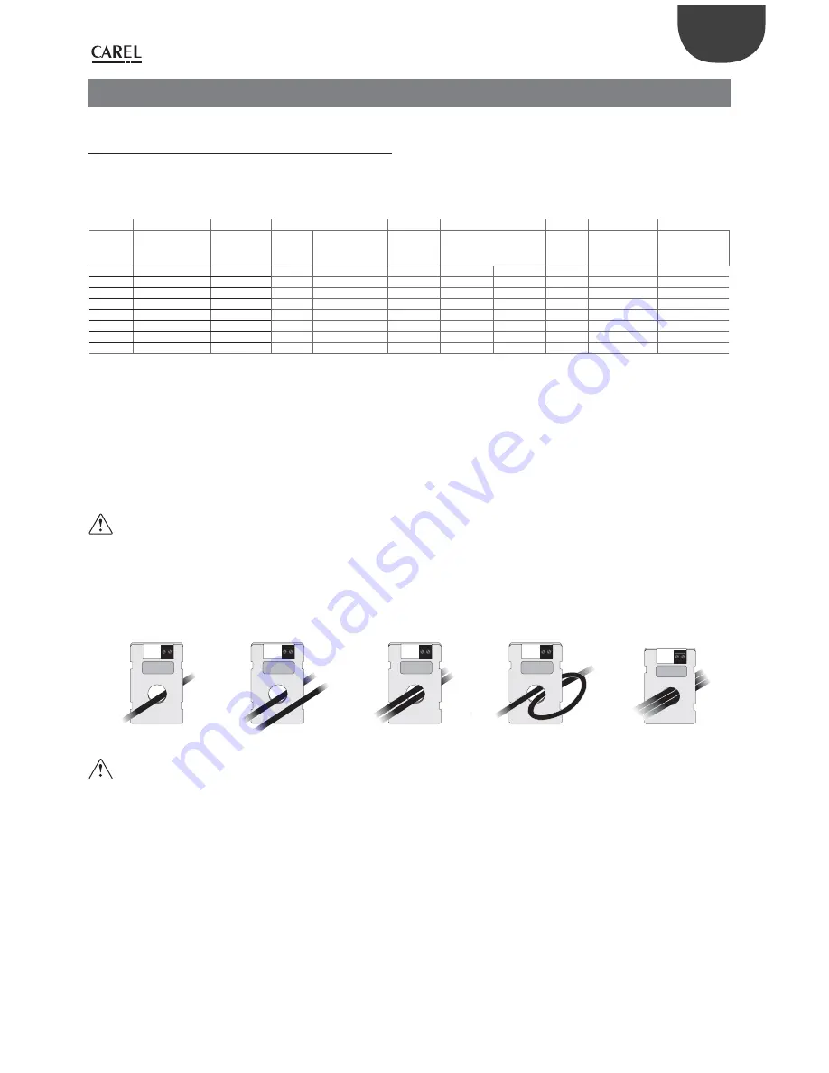
TAM configurations and connections (transformer for
measuring the current)
Important
: the configurations and connections are already made
by CAREL, and no changes are required. The following diagrams
represent possible connection modes and may be useful in the event of
serious electrical malfunctions on the humidifier.
All operations must only be performed by qualified personnel, improper
use may cause serious damage.
one cable turn
one turn of the two
cables of the same phase
two cable turns of the
same phase
one cable in “double
turn” mode
three cable turns of the
same phase
700
500
300
100
700
500
300
100
700
500
300
100
700
500
300
100
700
500
300
100
Fig. 11.a
Fig. 11.b
Fig. 11.c
Fig. 11.d
Fig. 11.e
Important:
to avoid interference, separate the power cables
from the probe cables.


