background image

µRack 

Cod. CAREL +03P220431 rel. 0.0 del 08/09/05 - preliminary version


20

If, on the other hand, the cause of the alarms is still present, the initial situation will return. 

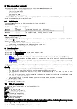
7.3.


Semiautomatic alarms 

The low pressure alarm from transducer is a semiautomatic alarm. It acts as an alarm with automatic reset, however if it is activated at least 3 times within a set 
time (default 10 minutes), it becomes an alarm that must be reset manually, that is, using parameter A19. This alarm obviously causes the unit to shutdown. 

7.4.


Alarm relay 

Based on the configuration (no. of devices < 5) relay no. 5 (multifunction) can be used as an alarm relay.  
A delay time can be set (parameter A20) between the activation of an alarm and the change in the status of the signal relay. 

If the time is set to 0, the activation of the alarm relay is immediate. 
 

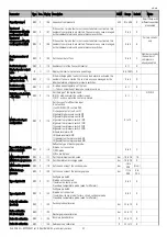
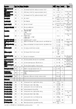
Code 

Alarm description 

Generated by 

Action performed 

Type of reset

Delay 

Notes 

A01 

Compressor 1 

DIN 

Comp.1 OFF 

Settable 

Settable 


A02 

Compressor 2 

DIN 

Comp.2 OFF 

Settable 

Settable 


A03 

Compressor 3 

DIN 

Comp.3 OFF 

Settable 

Settable 


A04 

Compressor 4 

DIN 

Comp.4 OFF 

Settable 

Settable 


A05 

Compressor 1 maintenance 

--- Comp.1 

OFF 

Settable 

no 


A06 

Compressor 2 maintenance 

--- Comp.2 

OFF 

Settable 

no 


A07 

Compressor 3 maintenance 

--- Comp.3 

OFF 

Settable 

no 


A08 

Compressor 4 maintenance 

--- Comp.4 

OFF 

Settable 

no 


A09 

Liquid level (from multifunction input)

DIN 

manual 

settable 


A10 

General suction pressure switch 1 

(from multifunction input) 

DIN 

COMP OFF CIRC 1  

automatic 

no 


A11 

General suction pressure switch 2 
(from multifunction input) 

DIN 

COMP OFF CIRC 2  

automatic 

no 


A12 

General discharge pressure switch 
(from multifunction input) 

DIN 

All comps. OFF  

Settable 

no 


A13 

Low discharge pressure 

AIN 

All fans OFF 

automatic 

settable 


A14 

High discharge pressure 

AIN 

All fans ON 

automatic 

no 


A15 

Low suction pressure 1 

AIN 

All comps. OFF  

automatic 

settable 


A16 

High suction pressure 1 

AIN 

all comps. ON 

automatic 

settable 


A17 

Low suction pressure 2 

AIN 

All comps. OFF  

automatic 

settable 


A18 

High suction pressure 2 

AIN 

all comps. ON 

automatic 

settable 


A19 

Suction probe 1 faulty or disconnected 

AIN 

Settable no. comps. ON

manual 

30 seconds  See compressor management with probe broken. 

A20 

Suction probe 2 faulty or disconnected 

AIN 

Settable no. comps. ON

manual 

30 seconds  See compressor management with probe broken. 

A21 

Discharge probe faulty or disconnected 

AIN 

Settable no. fans ON

manual 

30 seconds  Force fan inverter to 100%. 

A22 

Fan 1 thermal overload 

DIN 

Fan 1 OFF 

Settable 

no 


A23 

Fan 2 thermal overload 

DIN 

Fan 2 OFF 

Settable 

no 


A24 

Fan 3 thermal overload 

DIN 

Fan 3 OFF 

Settable 

no 


A25 

Fan 4 thermal overload 

DIN 

Fan 4 OFF 

Settable 

no 


A26 

General fan thermal overload  

DIN 

All fans OFF 

automatic 

no 


A27 

Prevent high discharge pressure  AIN Compressors 

OFF 

automatic no 


A28 

Compressors off for Prevent HP 

AIN 

Compressors OFF 

automatic 

no 


A29 

Excessive prevent frequency 

AIN 

settable 

no 

Display only 

HtE High 

outside 

temperature 

AIN 


Automatic  No   

HtA 

High ambient temperature 

AIN 


Automatic 

No 


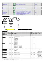
7.5.


Alarms from analogue inputs: temperature probe and pressure transducer: 

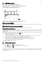
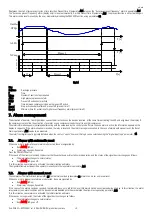
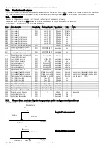
fixed differentials: 


 0.2 bar suction 


 1.0 bar discharge 


High press. 

Alarm off 

Set Point 

Alarm on 

Diff. 

Example of HP alarm management 

Low press.

Alarm off 

Set Point 

Alarm on 

Diff. 

Example of LP alarm management 

Summary of Contents for mRack

Page 1: ...µRack Standard compressor racks single two circuit ...

Page 2: ......

Page 3: ...ce that are not authorised by the manufacturer are considered incorrect Liability for injury or damage caused by the incorrect use of the device lies exclusively with the user Please note that this unit contains powered electrical devices and therefore all service and maintenance operations must be performed by specialist and qualified personnel who are aware of the necessary precautions Disconnec...

Page 4: ......

Page 5: ...3 Example of compressors with different capacities 11 4 6 Manually enable disable the compressors 12 4 7 Special MT LT units 12 4 7 1 Management of compressor racks with LT and MT circuits and condenser only 12 4 7 2 Probes and values controlled 12 4 8 Compressor time settings 13 5 1 Fan management 14 5 1 1 Fan control 14 5 2 Dead band control 14 5 2 1 5 1 2 Fan rotation 14 5 3 Inverter management...

Page 6: ... 20 8 1 Serial boards 21 8 2 Communication protocols 21 7 Alarm management 19 8 The supervisor network 21 9 User interface 21 10 List of parameters 21 11 ON OFF fan control board code CONVONOFF0 28 12 PWM to 0 to 10 Vdc or 4 to 20 mA conversion board for fans code CONV0 10A0 28 13 Programming key code PSOPZKEYA0 29 14 Supervisor management 29 15 Default configurations 32 16 Glossary 32 ...

Page 7: ...generic alarm as automatic manual 13 Enable compressors from the Maintenance screen 14 Proportional plus integral function for the fan inverter 15 Floating condenser set point 16 Optional temperature probes with high temperature alarm threshold a Outside air b Ambient air c Compressor discharge temperature d Suction temperature 1 2 Main characteristics Main functions Control of compressor suction ...

Page 8: ...point to display the monitored values and ICONS for the status of the devices and operating modes As well as displaying the values measured and the operating conditions of the unit the user terminal display and keypad can be used to modify the unit operating parameters The following figures show the µRack for panel installation and for DIN rail mounting ...

Page 9: ...password for accessing the USER parameters b Press the button when the list of parameters is displayed to show the numeric value of the parameter c Press the button when the numeric value of a parameter is displayed to accept the numeric value and return to the list of parameters a Press the button to display the other controlled values The label of the probe will be displayed and then the numeric...

Page 10: ...he ALARM icon indicates the activation of the compressor alarms 1 Indicates the number of compressors on 2 If flashing indicates the ON OFF call for a new compressor step while the device is awaiting the expiry of the delay times 3 If the controller is used for fan control only 01 0 then the icon shows the status of the fans 3 Starting the unit 3 1 Starting for the first time After having checked ...

Page 11: ...ay by the message OFF switches the controller off stops the management of the various devices and the related alarms 3 3 Meaning of the inputs outputs 3 3 1 Table of analogue inputs The tables below describe the type of the probes that can be connected to the inputs and their characteristics Analogue inputs Input Description Type of probes that can be connected B1 Ratiometric discharge pressure pr...

Page 12: ...µRack Cod CAREL 03P220431 rel 0 0 del 08 09 05 preliminary version 8 Analogue outputs Outputs Description Y1 Fans speed controller PWM 3 3 2 Wiring diagrams Panel installation DIN rail installation ...

Page 13: ...IFO rotation The first compressor to start will be the last to stop Start C1 C2 C3 C4 Stop C4 C3 C2 C1 FIFO rotation The first compressor to start will be the first to stop Start C1 C2 C3 C4 Stop C1 C2 C3 C4 This selection enables the rotation of the compressors so as to even out as much as possible the number of compressor operating hours Rotation by time The compressor that starts will be the on...

Page 14: ...r r07 Pressure differential within which the time varies parameter r11 Maximum compressor off time parameter r10 Minimum compressor off time parameter r09 Fig 4 3 Key InPress Suction pressure DTNZ Differential within which the time varies STPM Control set point TOnMax Maximum compressor on time RBM Control band TOnMin Minimum compressor on time NZ Dead band TOffMax Maximum compressor off time DOnZ...

Page 15: ...e the capacity required to bring the pressure back near the set point At the set point plus differential the requirement will be at the maximum value while it will be null for pressure values around or less than the set point al Differenti press Setpoint Capacity Max required Capacity _ _ 4 5 2 Dead band control with different capacity compressors The software will calculate the maximum number of ...

Page 16: ...compact and offering low cost solutions These are compressor racks with only the condensing section and with fan speed managed by the speed controller or external pressure switches and separate management of the compressors in the MT and LT units Below is an example diagram This type of system can be controlled by µrack in the following conditions 1 the compressors must have the SAME CAPACITY 2 th...

Page 17: ...starts of different compressors proportional band This represents the minimum time that must elapse between the start of one device and the next This parameter allows simultaneous starts to be avoided parameter C03 Minimum time between starts of the same compressor Sets the minimum time that must elapse between two starts of the same compressor This parameter limits the number of starts per hour I...

Page 18: ... band to the side of the set point within which no device is started or stopped The devices are activated when the measured value exceeds the limit to the right measured value greater than SP DZN see Figure 5 2 The number of devices to be activated varies according to the time elapsed outside of the dead band The first device will start immediately while the others will wait the set time between s...

Page 19: ...r set point STPI to be set parameter r18 plus an inverter differential RBI parameter r19 If the value measured by the discharge probe is less than or equal to the value of the inverter set point the inverter output will be 0 Between the inverter set point STPI and point C set point differential the value of the inverter output will be proportional to the value read by the discharge probe and in an...

Page 20: ...Pressure read SP Set point T Time Min In Minimum inverter output value Dead band control This control requires the setting of inverter set point the inverter pressure differential for dead band control parameter r21 and the inverter ramp up time parameter r28 Three zones are defined activation zone DOnZ dead band NZ and deactivation zone DOffZ in which the program behaves differently see the figur...

Page 21: ...fferent motors existing on the market the voltages supplied by the electronic board that correspond to the minimum and maximum speed can be set For this purpose and if the default values are not suitable proceed as follows 1 Set the fan inverter to always On Force inverter parameter M17 2 Set Max triac and Min triac to zero 3 Increase Max triac until the fan operates at a speed considered sufficie...

Page 22: ...d using parameter C16 6 4 Type of refrigerant By selecting the type of refrigerant used in the installation parameter 35 the software will automatically calculate the conversion of the pressure to temperature The following table lists the types of gas managed Refrigerant Complete name R134a Tetrafluoroethane R290 Propane R600 Butane R600a 2 methyl propane isobutane R717 Ammonia NH3 R744 Carbon dio...

Page 23: ...h manual reset the Reset Alarms parameter A19 needs to be accessed The alarm from digital input is typically detected when the contact opens however the logic can be selected using the digital input logic parameter 14 7 1 Alarms with automatic reset When one or more automatic reset alarms are detected these are signalled by Red ALARM LED on Alarm relay changes if enabled Press the PRG MUTE button ...

Page 24: ...unction input DIN COMP OFF CIRC 2 automatic no A12 General discharge pressure switch from multifunction input DIN All comps OFF Settable no A13 Low discharge pressure AIN All fans OFF automatic settable A14 High discharge pressure AIN All fans ON automatic no A15 Low suction pressure 1 AIN All comps OFF automatic settable A16 High suction pressure 1 AIN all comps ON automatic settable A17 Low suct...

Page 25: ...f the devices connected times set points differentials 2 INSTALLER parameters password 44 modifiable by parameter 41 periodical checks on the devices calibration of the probes connected manual operation of the devices 3 MANUFACTURER parameters password 77 modifiable by parameter 42 configure the compressor rack enable the main functions and select the devices connected Once the password is entered...

Page 26: ...t model SINGLE CIRCUIT 0 0 compressors 1 1compressor 2 2 compressors 3 3 compressors 4 4 compressors TWO CIRCUIT 5 1 compressor 1 compressor 6 2 compressors 1 compressor 7 3 compressors 1 compressor 8 2 compressors 2 compressors 0 to 8 2 Compressors with different capacities R W C 02 Enable management of compressors with different capacities 0 NOT ENABLED 1 ENABLED 0 1 0 For single circuit only Ca...

Page 27: ...igital inputs 0 N O with no alarm the contact is open 1 N C with no alarm the contact is closed 0 1 1 NO NC Multifunction input configuration R W C 15 Set the type of multifunction input 0 no function 1 unit ON OFF NC contact ON 2 change set point set1 set2 3 general high pressure switch NC 4 general high pressure switch NO 5 general low pressure switch 1 NC 6 general low pressure switch 1 NO 7 ge...

Page 28: ...her to display the parameters in 0 bar C 1 psi F bar psi 0 1 0 Refrigerant conversion R W C 35 Type of refrigerant used 0 No refrigerant 1 R22 2 R134a 3 R404a 4 R407c 5 R410a 6 R507 7 R290 8 R600 9 R600a 10 R717 11 R744 0 to 11 3 Serial address R W C 36 Supervisor configuration Identification number of the µRack board for the supervisor serial network 1 to 200 1 Delay restart after black out R W I...

Page 29: ...ompressor set point 2 Offset R W I C16 Auxiliary compressor set point offset Used when changing the set point from digital input bar 99 9 to 99 9 0 Control menu Compressor set point circuit 1 R W U r01 Compressor set point first circuit bar C mintomax comp set 1 0 Compressor differential circuit 1 R W U r02 compressor differential first circuit bar C 0 to 20 0 0 5 Compressor set point circuit 2 R ...

Page 30: ... of the fan set point bar C 0 to r27 0 to r27 1 0 31 2 Max fan set point R W C r26 Set the upper limit of the fan set point bar C r26 to 40 0 r26 to 150 25 0 55 3 Fan inverter speedup time R W C r27 Fan inverter speedup time s 0 to 999 2 Only if the inverter is enabled Inverter ramp up time R W I r28 Set the time taken by the inverter to reach full load s 0 to 999 10 Only if the inverter is enable...

Page 31: ...1 0 Alarm signal delay R W I A20 Set alarm signal delay s 0 to 999 1 Exchange auto man LP 3 alarms R W I A21 On the 3rd activation within the set time the low pressure alarm from pressure switch changes from automatic to manual reset m 0 to 999 10 Off due to probe disconnected R W I A22 Enable unit OFF due to probe disconnected alarm 0 NO 1 YES 0 1 0 Maintenance menu Enable compressor 1 R W I M01 ...

Page 32: ...W I M17 Manually operate the inverter at 100 0 NO 1 YES 0 1 0 Only if the inverter is enabled Tab 10 1 11 ON OFF fan control board code CONVONOFF0 The CONVONOFF0 modules allow the ON OFF control of the condenser fans The control relay has a switching power 10A at 250 Vac in AC1 1 3 HP inductive 12 PWM to 0 to 10 Vdc or 4 to 20 mA conversion board for fans code CONV0 10A0 The CONV0 10A0 modules con...

Page 33: ...visor telemaintenance system for managing the unit The variables sent and received by the supervisor are shown in the tables below with reference to the following key R Read Send from the µRack to the supervisor Not modifiable R W Read Write Received and sent from the µRack to the supervisor Can be modified by the supervisor Analogue variables Flow Index Description R 1 Probe B4 R 2 Probe B1 R 3 P...

Page 34: ...R 14 Status of digital input 5 R W 15 Reset alarms A19 R W 16 Digital input logic 14 R W 17 Alarm relay logic 28 R W 18 Enable fan inverter 10 R W 19 ON OFF from supervisor R W 20 Enable prevent control on condenser 32 R W 21 Enable management of different compressors 02 R W 22 Type of compressor reset 29 R W 23 Type of fan reset 30 R W 24 Type of reset for general high press switch 31 R W 25 Rese...

Page 35: ...f different compressors C03 R W 11 Minimum time between starts of the same compressor C05 R W 12 Fan start delay dead band r23 R W 13 Fan stop delay dead band r24 R W 14 Liquid level alarm delay A18 R W 15 Minimum fan speed R W 16 Number of compressors on in circuit 1 with probe damaged 07 R W 17 Number of compressors on in circuit 2 with probe damaged 08 R W 18 Number of fans on with probe damage...

Page 36: ... no 5 General high pressure switch Signal type of digital outputs Description NO1 normally open contact relay no 1 Compressor 1 NO2 normally open contact relay no 2 Compressor 2 NO3 normally open contact relay no 3 Fan 1 NO4 normally open contact relay no 4 Fan 2 NO5 normally open contact relay no 5 Generic alarm 16 Glossary Analogue value integer value with minus sign and decimal point Buffer mem...

Page 37: ...µRack Cod CAREL 03P220431 rel 0 0 del 08 09 05 preliminary version 33 ...

Page 38: ...µRack Cod CAREL 03P220431 rel 0 0 del 08 09 05 preliminary version 34 CAREL SpA reserves the right to make modifications or changes to its products without prior notice ...

Page 39: ......
Page 40: ...CAREL S p A Via dell Industria 11 35020 Brugine Padova Italy Tel 39 049 9716611 Fax 39 049 9716600 http www carel com e mail carel carel com Agency 03P220431 rel 00 del 08 09 05 preliminary version ...

Reviews: