µRack
Cod. CAREL +03P220431 rel. 0.0 del 08/09/05 - preliminary version
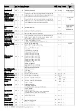
32
R/W
43
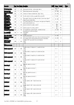
Type of fan control “r21”
R/W
44
Integral time for P+I fan control “r22”
R/W
45
Time between 2 fans starts in dead band “r23”
R/W
46
Time between 2 fans stops in dead band “r24”
R/W
47
Inverter speed up time “r27”
R/W
48
Inverter ramp up time “r28”
R/W
49
Minimum inverter output % “r29”
R/W
50
Maximum inverter output % “r30”
R/W
51
Triac impulse duration “r31”
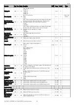
R/W
52
High suction pressure 1 alarm delay “A02”
R/W
53
Low suction pressure 1 alarm delay “A04”
R/W
54
High suction pressure 2 alarm delay “A06”
R/W
55
Low suction pressure 2 alarm delay “A08”
R/W
56
Low discharge pressure alarm delay “A11”
R/W
57
Compressor thermal overload alarm delay “A12”
R/W
58
Prevent time in which no compressor starts are enabled “A13”
R/W
59
Prevent time in which the activation signals the alarm “A14”
R/W
60
Time to reset prevent alarm “A15”
R/W
61
Alarm signal delay “A20”
R/W
62
Time to change low pressure alarm from automatic to manual “A21”
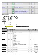
15.
Default configurations
Signal
type of analogue inputs
description
B1
analogue input 1
Discharge pressure probe
B2
analogue input 2
Ambient air temperature probe
B3
analogue input 3
Outside air temperature probe
B4
analogue input 4
Suction pressure probe
Signal
type of analogue outputs
description
Y
PWM analogue output
Fan inverter
Signal
type of digital inputs
Description
ID1
N.C. digital input no. 1
Comp. 1 thermal overload
ID2
N.C. digital input no. 2
Comp. 2 thermal overload
ID3
N.C. digital input no. 3
Fan 1 thermal overload
ID4
N.C. digital input no. 4
Fan 2 thermal overload
ID5
N.C. digital input no. 5
General high pressure switch
Signal
type of digital outputs
Description
NO1
normally open contact, relay no. 1
Compressor 1
NO2
normally open contact, relay no. 2
Compressor 2
NO3
normally open contact, relay no. 3
Fan 1
NO4
normally open contact, relay no. 4
Fan 2
NO5
normally open contact, relay no. 5
Generic alarm
16.
Glossary
Analogue value: integer value with minus sign and decimal point.
Buffer (memory): memory on the board used to save the default values selected by CAREL for all the parameters. Permanent memory, saves the values even when
power is disconnected.
Buzzer: buzzer fitted on the external terminals; this sounds in the event of alarms or the limits set for the parameters are exceeded. The Built-in terminals do not
have a buzzer.
Digital value: value with only two states.
Differential: defines a pressure (or temperature) difference from the corresponding set point.
Discharge: pressure or temperature measured at the compressor outlet. This is an analogue value.
HP : High pressure
Integer value: integer value without decimal point.
LP : Low pressure
Proportional band: this defines a temperature (or pressure) zone of a few degrees starting from the set point, inside which the system manages the control devices.
Range: range of values available for a parameter.
Step: defines an area of the proportional band (pressure or temperature) inside which a device is on, and at the same time also defines the device on/off values.
Set point: defines a pressure (or temperature) value to be satisfied; the system activates or deactivates the devices so that the value measured reaches the set point.
Suction: pressure or temperature measured at the compressor intake. This is an analogue value.
Upload: the operation used to copy the application software from the computer or programming key to the Rack.
Summary of Contents for mRack
Page 1: ...µRack Standard compressor racks single two circuit ...
Page 2: ......
Page 4: ......
Page 37: ...µRack Cod CAREL 03P220431 rel 0 0 del 08 09 05 preliminary version 33 ...
Page 39: ......

