17
ENG
“optiMist” +0300065EN - rel. 1.6 - 18/06/2021
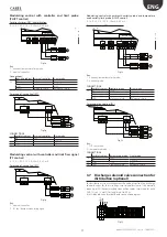
Modulating control with controller and limit probe
(PH/PT control)
For direct/winter (DEC) humdification:
0...1 V; 0...10 V; 2...10 V; 0...20 mA; 4...20 mA
J9
J10
J12
J11
J13
J14
J15
SERIAL CARD
J9
J24
J2
J3
J4
J5
J16
J17
J18
J6
J7
J21
J22
J20
J19
FIELD CARD
pCO3
1
2
/T
B B B
B B B
B
Fig. 3.o
Key:
1.
humidity/temperature limit probe
2.
external controller
Connections:
optiMist cabinet External controller
Limit probe
J2
B1
OUT
B2
OUT H/T
+Vdc
+(G)
GND
Reference, shield
Reference, shield
For evaporative cooling (IEC),
J2
J6
B6
B7
B8
GND
1
2
+(G)
M
out H
REF
OUT
Fig. 3.p
CONNECTIONS
optiMist cabinet
External controller
Limit probe
J6
B6
OUT
B7
OUT H/T
J2
+Vdc
+(G)
J6
GND
Reference, shield
Reference, shield
Modulating control with controller and limit flow signal
(PF control)
0...1 V; 0...10 V; 2...10 V; 0...20 mA; 4...20 mA
For evaporative cooling (IEC),
J2
J6
B6 B7 B8 GND
+VDC
2
REF
OUT
1
REF
OUT
Fig. 3.q
Key:
1.
external controller.
2.
IEC fan / damper modulating signal
Modulating control with ambient humidity probe and temperature
and humidity limit probe (HH/HT control)
0...1 V; 0...10 V; 2...10 V; 0...20 mA; 4...20 mA
For direct/winter (DEC) humdification:
J9
J10
J12
J11
J13
J14
J15
SERIAL CARD
J9
J24
J2
J3
J4
J5
J16
J17
J18
J6
J7
J21
J22
J20
J19
FIELD CARD
pCO3
1
2
/T
B B B
B B
B B
Fig. 3.r
Key:
1.
humidity/temperature limit probe;
2.
humidity probe .
CONNECTIONS
:
optiMist cabinet Humidity probe
Limit probe
J2
B1
OUT H
B2
OUT H/T
+Vdc
+(G)
+(G)
GND
Reference, shield
Reference, shield
For evaporative cooling (IEC):
J2
J6
B6
B7
B8
GND
1
2
+(G)
M
out H
+(G)
M
out H
Fig. 3.s
Key:
1.
H/T limit probe;
2.
temperature probe.
CONNECTIONS
:
optiMist cabinet Temperature probe Limit probe
J6
B6
OUT T
B7
OUT H/T
J2
+Vdc
+ (G)
+ (G)
J6
GND
Reference, shield
Reference, shield
3.7 Discharge solenoid valve connection for
distribution (optional)
For distribution system management, the cabinet controls the discharge
solenoid valves for the two steps: two solenoid valves of the normally
open type (NO). Recommended connection cables: two-wire plus earth
AWG13 (sec. 1.5 mm2) for lengths up to 100 m.
Insert solenoid valve terminal board connection diagram.
NO1
NO2
G0 G0
Fig. 3.t

