background image

Summary of Contents for UA HD3 Series

Page 1: ...D3 UA HD4 UA HD3 UA HD4 pump replacement NO POWER SIGNAL CABLES TOGETHER READ CAREFULLY IN THE TEXT MANUALE D USO USER MANUAL UA HD3 UA HD4 pump replacement 0300069IE ITA ENG Up to date version available on www carel com ...

Page 2: ......

Page 3: ...lle etichette dati di targa del prodotto Il prodotto è progettato esclusivamente per umidificare ambienti in modo diretto o mediante sistemi di distribuzione condotte Inoltre per gli umidificatori adiabatici atomizzatori ad acqua in pressione è prevista anche l umidificazione attraverso il telaio di atomizzazione Installazione utilizzo e manutenzione devono essere eseguite da personale qualificato...

Page 4: ...perevitarepossibili disturbi elettromagnetici Non inserire mai nelle stesse canaline comprese quelle dei quadri elettrici cavi di potenza e cavi di segnale Fig 1 Fig 2 SMALTIMENTO INFORMAZIONISULCORRETTOSMALTIMENTODEIRIFIUTIDIAPPARECCHIATUREELETTRICHEEDELETTRONICHE RAEE Ilprodottoècompostodapartiinmetalloedapartiinplastica InriferimentoallaDirettiva2002 96 CEdelParlamentoEuropeoedelConsigliodel27g...

Page 5: ...a cod UAK 6 1 2 Pompa in OTTONE assemblata cod UAK D00SP UAK D10SP UAK Y00 UAK Y10 9 1 3 Pompa in INOX cod UAK D41SP e UAK D42SP 11 1 4 Pompa in INOX cod UAK D01SP UAK D11SP UAK D12SP UAK Y01 UAK Y11 UAK Y12 14 2 Configurazione inverter 16 2 1 Tabella parametri inverter 16 2 2 Tabella codici ricambi tenute valvole e guarnizioni 16 ...

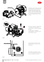
Page 6: ...e con l alimentazione dell acqua chiusa Rimuovere il blocco motore pompa dall unità scollegando i tubi idraulici cavi elettrici e viti di fissaggio del motore alla base Fig 1 a A B B A A B A B Rimuovere la pompa dal motore to gliendo le 4 viti M8 sulla flangia A Nel caso in cui lo sfilamento della pompa dal motore risultasse difficoltoso si possono utilizzare le viti della flangia precedentemente ...

Page 7: ...re la nuova pompa al motore come nella figura facendo attenzione all allineamento della chiavetta del motore con la cavità dell albero della pompa Ungere con del grasso l albero del motore per facilitare l inserimento I 4 bulloni della flangia vanno serrati a 10Nm Fig 1 d Assemblare il gruppo Alta Pressione manometro valvola regolazione Bypass trasduttore e pressostato alla pompa tramite raccordo ...

Page 8: ...iallo con asta di livello in dotazione al ricambio pompa Accedere al Menu Installatore maschera Baa02 e selezionare SI sulla riga Cambiare pompa Fig 1 f Eseguire foro diam 35mm in corris pondenza dell uscita Alta Pressione della pompa Ricollegare la parte elettrica del mo tore e successivamente le parti idrauli che precedentemente scollegate Fig 1 g ...

Page 9: ...e con l alimentazione dell acqua chiusa Rimuovere il blocco motore pompa dall unità scollegando i tubi idraulici cavi elettrici e viti di fissaggio del motore alla base Fig 1 h A B B A A B A B Rimuovere la pompa dal motore to gliendo le 4 viti M8 sulla flangia A Nel caso in cui lo sfilamento della pompa dal motore risultasse difficoltoso si possono utilizzare le viti della flangia precedentemente ...

Page 10: ... per facilitare l inserimento I 4 bulloni della flangia vanno serrati a 10Nm Fig 1 j Rimuovere il tappo rosso dalla pompa sostituendolo con quello giallo con asta di livello in dotazione al ricambio pompa Accedere al Menu Installatore maschera Baa02 e selezionare SI sulla riga Cambiare pompa Fig 1 k Eseguire foro diam 35mm in corris pondenza dell uscita Alta Pressione della pompa Ricollegare la pa...

Page 11: ...ne dell acqua chiusa Rimuovere il blocco motore pompa dall unità scollegando i tubi idraulici cavi elettrici e viti di fissaggio del motore alla base Fig 1 i A B B A A B A B Rimuovere la pompa dal motore togliendo le 4 viti M8 sulla flangia Nel caso in cui lo sfilamento della pompa dal motore risultasse difficoltoso si possono utilizzare i 4 estrattori filettati cerchio grigio utilizzando le viti ...

Page 12: ... abbia il grano visibile dalla fessura della flangia In caso contrario procedere all allinea mento Assemblare la nuova pompa al motore come nella figura facendo attenzione all allineamento della chiavetta del motore con il giunto elastico e i grani Ungere con del grasso l albero del motore per facilitare l inserimento Fig 1 l GRAIN TO BE FIXED GRANO DA FISSARE Fissare il giunto elastico attraverso...

Page 13: ...pompa al raccordo girevole già pre sente nella pompa di ricambio Fig 1 n Rimuovere il tappo rosso dalla pompa sostituendolo con quello giallo con asta di livello in dotazione al ricambio pompa Accedere al Menu Installatore maschera Baa02 e selezionare SI sulla riga Cambiare pompa Ricollegare la parte elettrica del motore e successivamente le parti idrauliche precedentemente scollegate Fig 1 o ...

Page 14: ...on l alimentazione dell acqua chiusa Rimuovere il blocco motore pompa dall unità scollegando i tubi idraulici cavi elettrici e viti di fissaggio del motore alla base Fig 1 p A B B A A B A B Rimuovere la pompa dal motore togliendo le 4 viti M8 sulla flangia Nel caso in cui lo sfilamento della pompa dal motore risultasse difficoltoso si possono utilizzare i 4 estrattori filettati cerchio grigio util...

Page 15: ...stico e i grani Ungere con del grasso l albero del motore per facilitare l inserimento Fig 1 r GRAIN TO BE FIXED GRANO DA FISSARE Fissare il giunto elastico attraverso la fessura sulla campana con chiave esa gonale da 4mm alla forza di serraggio di 6Nm Fissare le viti della frangia al motore alla forza di serraggio di 10Nm Fig 1 s Rimuovere il tappo rosso dalla pompa sostituendolo con quello giall...

Page 16: ...la cifra da cambiare e tramite le frecce up e down selezionare il valore corretto 9 Premendo il tasto RESET ENTER ESC quando si è impostato correttamente il valore si torna a visualizzare il nome del parametro cambiato 10 Seguire i passi 7 8 e 9 per ogni parametro da cambiare seguendo la tabella qui sotto solo per i modelli che necessi tano il cambio parametri 11 Confermare questo valore con RESET...

Page 17: ...SP UA600 4 1 UA600 3 1 UAKP600D 1SP UAKP600Y 1 UAKVGX1802SP UA1K0 4 1 UAK1K0D 1SP UAKVGX1802SP Tab 2 b codice unità cod Pompa Inox Carel ricambi tenute per pompa inox UA100 4 2 UA100 3 2 UAKP100D 2SP UAKP100Y 2 UAKVGX1502SP UA200 4 2 UA200 3 2 UAKP200D 2SP UAKP200Y 2 UAKVGX1502SP UA320 4 2 UA320 3 2 UAKP320D 2SP UAKP320Y 2 UAKVGX1502SP UA460 4 2 UA460 3 2 UAKP460D 2SP UAKP460Y 2 UAKVGX1802SP UA600...

Page 18: ......

Page 19: ...s must conform to the values specified on the product rating labels The product is designed exclusively to humidify rooms either directly or through distribution systems ducts Furthermore humidification via the atomising rack is also available for pressurised water adiabatic humidifiers Only qualified personnel who are aware of the necessary precautions and able to perform the required operations ...

Page 20: ... cables from cables to inductive loads and power cables so as to avoid possible electromagnetic disturbance Never run power cables including the electrical panel cables and signal cables in the same conduits Fig 1 Fig 2 DISPOSAL INFORMATION FOR USERS ONTHE CORRECT HANDLING OFWASTE ELECTRICAL AND ELECTRONIC EQUIPMENT WEEE The product is made up of metal parts and plastic parts In reference to Europ...

Page 21: ...N UAK 6 1 2 Assembled BRASS pump P N UAK D00SP UAK D10SP UAK Y00 UAK Y10 9 1 3 Stainless steel pump P N UAK D41SP and UAK D42SP 11 1 4 Stainless steel pump P N UAK D01SP UAK D11SP UAK D12SP UAK Y01 UAK Y11 UAK Y12 14 2 Inverter configuration 16 2 1 Inverter parameter table 16 2 2 Seal spare part number table valves and gaskets 16 ...

Page 22: ...off and with the water supply closed Remove the motor pump block from the unit disconnecting the water hoses wiring and screws fixing the motor to the base Fig 1 a A B B A A B A B Remove the pump from the motor by unscrewing the four M8 bolts on the flange A If the pump is hard to remove from the motor use the previ ously removed flange bolts on the four threaded disassembly points B Fig 1 b ...

Page 23: ...Assemble the new pump to the motor as shown in the figure making sure the motor key is aligned with the keyway on the pump shaft Grease the motor shaft to make assembly easier The four flange bolts must be tightened to 10 Nm Fig 1 d Fit the high pressure assembly pressure gauge bypass control valve transducer and pressure switch to the pump using the swivel fitting supplied with the replacement pu...

Page 24: ...ng it with the yellow one that includes the dipstick supplied with the replacement pump Access the Installer Menu screen Baa02 and select YES for Change pump Fig 1 f Drill a 35 mm hole at the pump high pressure outlet Reconnect the previously disconnect ed motor wiring and water connec tions Fig 1 g ...

Page 25: ...f and with the water supply closed Remove the motor pump block from the unit disconnecting the water hoses wiring and screws fixing the motor to the base Fig 1 h A B B A A B A B Remove the pump from the motor by unscrewing the four M8 bolts on the flange A If the pump is hard to remove from the motor use the previ ously removed flange bolts on the four threaded disassembly points B Fig 1 i ...

Page 26: ...ft to make assembly easier The four flange bolts must be tightened to 10 Nm Fig 1 j Remove the red cap from the pump replacing it with the yellow one that includes the dipstick supplied with the replacement pump Access the Installer Menu screen Baa02 and select YES for Change pump Fig 1 k Drill a 35 mm hole at the pump high pressure outlet Reconnect the previously disconnect ed motor wiring and wa...

Page 27: ...ith the water supply closed Remove the motor pump block from the unit disconnecting the water hoses wiring and screws fixing the motor to the base Fig 1 m A B B A A B A B Remove the pump from the motor by unscrewing the four M8 bolts on the flange If the pump is hard to remove from the motor use the four threaded extractors grey circle using the previously removed flange bolts Fig 1 n ...

Page 28: ...y assembled on the pump has the dowel visible from the slot on the flange If not carry out alignment As semble the new pump to the motor as shown in the figure making sure the motor key is aligned with the elas tic joint and the dowels Grease the motor shaft to make assembly easier Fig 1 p GRAIN TO BE FIXED GRANO DA FISSARE Secure the elastic joint through the slot on the bell using a 4 mm hex spa...

Page 29: ... to the pump using the swivel fitting supplied with the replacement pump Fig 1 r Remove the red cap from the pump replacing it with the yellow one that includes the dipstick supplied with the replacement pump Access the Installer Menu screen Baa02 and select YES for Change pump Reconnect the previously disconnected motor wiring and water connections Fig 1 s ...

Page 30: ...power off and with the water supply closed Remove the motor pump block from the unit disconnecting the water hoses wiring and screws fixing the motor to the base Fig 1 t A B B A A B A B Remove the pump from the motor by unscrewing the four M8 bolts on the flange If the pump is hard to remove from the motor use the four threaded extractors grey circle using the previously removed flange bolts Fig 1...

Page 31: ...as tic joint and the dowels Grease the motor shaft to make assembly easier Fig 1 v GRAIN TO BE FIXED GRANO DA FISSARE Secure the elastic joint through the slot on the bell using a 4 mm hex spanner with a tightening torque of 6 Nm Fix the flange bolts to the motor with a tightening torque of 10 Nm Fig 1 w Remove the red cap from the pump replacing it with the yellow one that includes the dipstick s...

Page 32: ...then use the up and down arrows to select the correct value 9 Press RESET ENTER ESC when the correct value has been set the display will show the parameter name again 10 Follow steps 7 8 and 9 for each parameter to be modified with reference to the table below only for models where the parameters need to be modified 11 Confirm the value by pressing RESET ENTER ESC The display will return to E1 04 ...

Page 33: ... UA600 3 1 UAKP600D 1SP UAKP600Y 1 UAKVGX1802SP UA1K0 4 1 UAK1K0D 1SP UAKVGX1802SP Tab 2 b Unit part number Carel stainless steel pump P N stainless steel pump seal spare parts UA100 4 2 UA100 3 2 UAKP100D 2SP UAKP100Y 2 UAKVGX1502SP UA200 4 2 UA200 3 2 UAKP200D 2SP UAKP200Y 2 UAKVGX1502SP UA320 4 2 UA320 3 2 UAKP320D 2SP UAKP320Y 2 UAKVGX1502SP UA460 4 2 UA460 3 2 UAKP460D 2SP UAKP460Y 2 UAKVGX18...

Page 34: ...REL INDUSTRIES Headquarters Via dell Industria 11 35020 Brugine Padova Italy Tel 39 049 9716611 Fax 39 049 9716600 e mail carel carel com www carel com UA HD4 pump replacement 0300069IE rel 1 0 30 09 2022 ...

Reviews: