2. MONTAGGIO
2.1 Ricevimento e conservazione
Controllare l’integrità dell’umidificatore alla consegna e notificare
immediatamente al trasportatore, per iscritto, ogni danno che possa
essere attribuito ad un trasporto incauto o improprio. Trasportare
l’umidificatore nel luogo di installazione prima di rimuoverlo dall’imballo,
afferrando il collo solo da sotto la base. Aprire la scatola di cartone,
togliere i distanziali di materiale antiurto e sfilare l’umidificatore,
mantenendola sempre in posizione verticale; rimuovere il sacchetto di
protezione solo prima dell’installazione.
2.2 Posizionamento
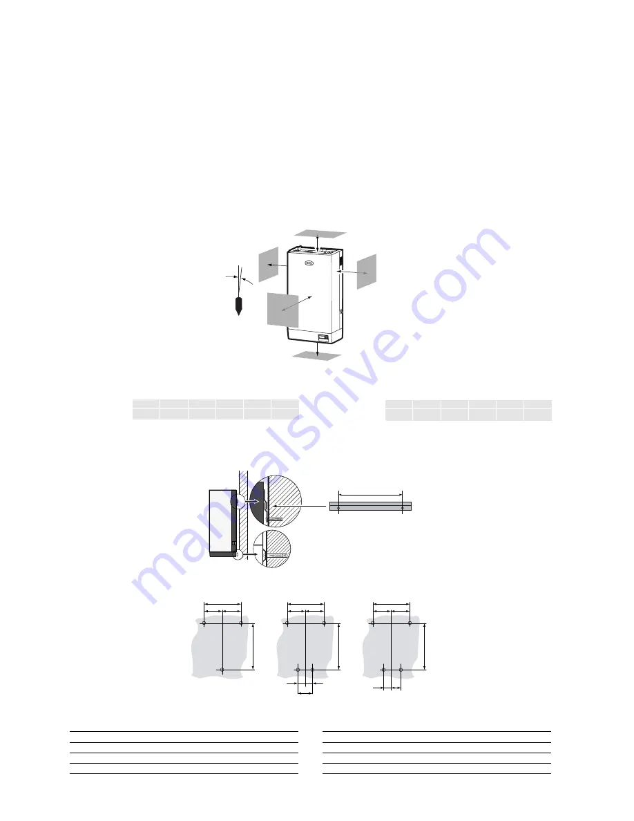
Scegliere per l’installazione la posizione più opportuna per la
distribuzione del vapore, ovvero quella che rende minima la lunghezza
del tubo di adduzione del vapore oppure, nel caso di umidificazione
diretta in ambiente mediante distributore
ventilato, in un punto baricentrico del locale
da umidificare (vedi il cap.4). L’unità è
progettata per un montaggio a parete la quale
deve avere una portata sufficiente per
sopportarne il peso in condizioni operative
(vedi il par.12.1).
L’involucro metallico dell’umidificatore durante
l’esercizio si riscalda e la parte posteriore
appoggiata alla parete può raggiungere
temperature superiori a 60 °C; assicurarsi,
quindi, che ciò non provochi alcun
inconveniente. Posizionare l’umidificatore in
bolla, osservando gli spazi minimi di rispetto
indicati nel disegno per consentire le
operazioni necessarie di manutenzione.
A
B
C
D
E
F
Dimensioni in mm
≥
300
≥
200
≥
200
≥
400
≥
700
<0,5°
2.3 Fissaggio
L’apparecchio deve essere montato a parete con tre viti: due superiori,
per il fissaggio della staffa di supporto,
ed una inferiore, centrale, per il
bloccaggio. Per le quote (in mm) vedi
fig. 2.3.1 Fissare a parete (vedi Figg.
2.3.1 e .2) la staffa compresa a
corredo dell’umidificatore, controllando
con una bolla che la sua posizione sia
orizzontale; se il montaggio viene
eseguito su parete in muratura,
possono essere adoperati i tasselli
plastici (Ø 8 mm) e le viti
(Ø 5 mm x L = 50 mm) in dotazione.
Appendere l’apparecchio alla
staffa utilizzando il profilo che si
trova sul bordo superiore dello
schienale. Assicurare infine
l’apparecchio alla parete per
mezzo del foro praticato sulla
mezzeria posteriore della base
(in basso), facilmente
raggiungibile dal fondo. Per i pesi
e le dimensioni vedi il par.12.1.
Modelli
UE 001...008
UE 009...015
UE 025...045
UE065
X
220
220
310
400
Y
500
590
725
785
Z
115
38
Z’
112
2. MOUNTING
2.1 Receipt and storage
Check that the humidifier is intact upon receipt and immediately notify
the shipping agent, in writing, of any damage that may be due to
improper or careless transport. Move the humidifier to the place of
installation before removing it from the packaging, grasping the neck
only from below the base. Open the box, remove the layer of protective
material and take out the humidifier, keeping it vertical at all times; only
remove the protective bag when installing the unit.
2.2 Positioning
For installation choose the most suitable position for the steam
distribution, that is the position that minimises the length of the steam
outlet pipe, or alternatively, in the case of direct humidification into the
room using a ventilated distributor, in a
central position in the room being humidified
(see Chap. 4). The unit has been designed for
wall-mounting, and the wall must be able to
support the weight of the unit in normal
operating conditions (see par. 12.1).
The metal casing of the humidifier heats up
during operation, and the rear part in contact
with the wall may reach temperatures of over
60 °C; check that this does not cause any
problems. Make sure the humidifier is level,
and that the minimum spaces are respected
as per the drawing, to allow room for
maintenance operations.
A
B
C
D
E
F
Dimension in mm
≥
300
≥
200
≥
200
≥
400
≥
700
<0,5°
2.3 Fastening
The appliance must be wall-mounted using three screws: two upper
screws, for fastening the support
bracket, and one lower, central screw,
to fasten the unit into place. For the
distances (in mm), see Fig. 2.2.1.1.
Fasten (see Figs. 2.3.1 and .2) the
bracket supplied with the humidifier to
the wall, checking that it is horizontal
using a spirit level; if the unit is
mounted on a brick wall, plastic screw
anchors (diam. 8mm) and the screws
(diam. 5mm x L= 50 mm) supplied
may be used.
Hang the appliance on the
bracket using the band located
on the top edge of the rear of
the unit.
Finally, fasten the appliance to
the wall using the central hole in
the rear part of the base; this
can be easily reached from
below.
For the weights and dimensions,
see par. 12.1.
Model
UE 001 to 008 UE 009 to 015 UE 025 to 045
UE065
X
220
220
310
400
Y
500
590
725
785
Z
115
38
Z’
112
10
humiSteam -
cod. +030221910 rel. 5.2 - 07.11.2005
A
B
C
D
E
F
staffa
bracket
X
=
X
Y
X
Y
Z
=
=
=
=
=
X
Y
Z
Z’
=
=
Fig. 2.2.1
Fig. 2.3.1
Fig. 2.3.2
Summary of Contents for UE001-065 humisteam
Page 2: ......
Page 78: ...78 humiSteam cod 030221910 rel 5 2 07 11 2005 ...
Page 79: ...79 humiSteam cod 030221910 rel 5 2 07 11 2005 ...


