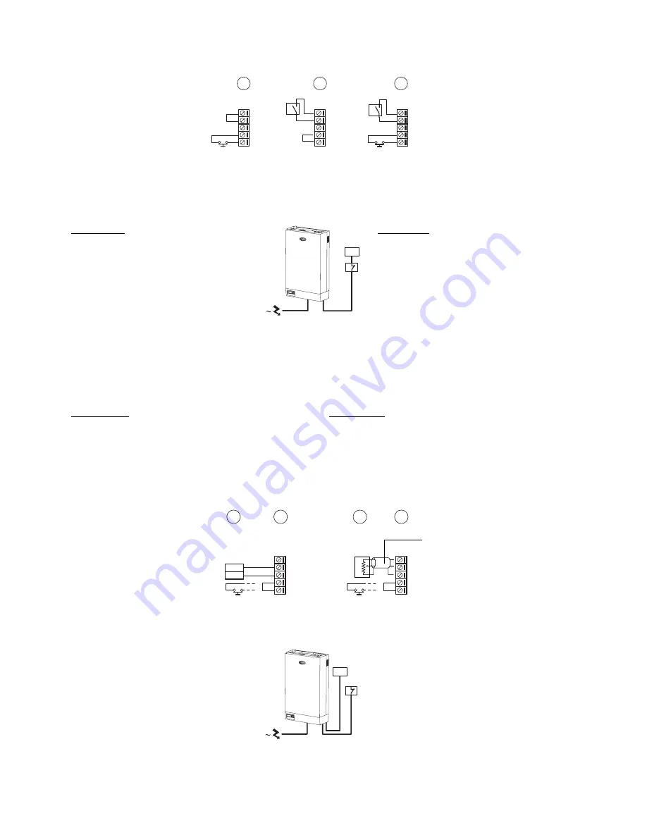
5.4 Segnali di comando dal campo
5.4.1 Controllore P: impiego con azione ON/OFF
L’umidificatore viene azionato dalla
chiusura di un umidostato meccanico
H oppure dalla chiusura di un contatto
remoto CR pulito (senza potenziale),
oppure da una combinazione dei due.
Per ulteriori dettagli si veda il
capitolo11.
Gli schemi di Fig. 5.4.1.1 mostrano i
collegamenti da realizzare sulla
morsettiera nei casi di:
a) azionamento pilotato da semplice
contatto di abilitazione;
b) azionamento per mezzo di umidostato meccanico esterno;
c) combinazione dei casi precedenti.
Contatto AB-AB:
• chiuso: l’umidificatore è abilitato alla produzione di
vapore quando l’umidostato si chiude;
• aperto: la produzione di vapore viene immediatamente
bloccata.
Il contatto di on/off remoto è di solito una serie di contatti
puliti che abilitano l’umidificatore quando tutti quanti
sono chiusi, indicando, in tal modo, che la condotta/UTA
è pronta a ricevere il vapore.
Per esempio:
• ventilatore: il contatto associato al ventilatore si chiude quandoil
ventilatore è in marcia;
• batteria di raffreddamento a valle dell’umidificatore: il contatto
associato è chiuso quando lal batteria è spenta;
• ecc.
Contatto VR-SET:
• chiuso: l’umidificatore produce vapore se anche il contatto AB-AB
è chiuso
• aperto: la produzione di vapore termina dopo il completamento del
ciclo di evaporazione in corso (max. 10-15 min dall’apertura del
contatto).
5.4.2 Controllore P: impiego con azione proporzionale
La produzione di vapore viene gestita
da un regolatore esterno R oppure da
un potenziometro P (valore nominale
minimo 5 k
Ω
- Fig. 5.4.2.2),
eventualmente integrati da un contatto
remoto CR senza potenziale.
Il regolatore esterno o il potenziometro
trasmettono al controllore un segnale
modulante consistente in una tensione
0...10 Vdc.
L’eventuale presenza del contatto
remoto CR permette l’arresto della
macchina indipendentemente dalla richiesta del
regolatore R o del potenziometro P (l’avvio della
macchina invece è subordinato al consenso di
entrambi questi dispositivi).
Per ulteriori dettagli a riguardo si rimanda al capitolo 11.
Gli schemi di Fig. 5.4.2.1 mostrano i collegamenti da
realizzare sulla morsettiera nei casi di:
a) azionamento pilotato da solo regolatore esterno R;
b) azionamento pilotato da solo potenziometro esterno P;
a) + c) azionamento pilotato da regolatore esterno R e
contatto remoto CR (che sostituisce il ponte indicato
nel disegno a);
b) + d) azionamento pilotato da potenziometro esterno P
e contatto remoto CR (che sostituisce il ponte indicato
nel disegno b).
5.4 External control signals
5.4.1 P controller: ON/OFF operation
The humidifier is operated by the
closing of a mechanical humidistat H,
or by the closing of a voltage-free
remote contact CR, or alternatively by
a combination of both. For further
details, see chapter 1.1.
The diagrams in Fig. 5.4.1.1 show the
connections to be made on the
terminal block, in the case of:
a) operation performed by a simple
enabling contact;
b) operation controlled by an external
mechanical humidistat;
c) a combination of the above.
Contact AB-AB:
• closed: humidifier enabled to produce steam
(production starts when humidostat closes);
• open: steam production is immediately stopped.
The remote on/off contact is usually a series of external
potential-free contacts that enable the humidifier to
produce steam when all of them are closed, indicating
the duct/AHU is ready to accepet steam.
For example,
• fan contact closes when fan is running;
• downstream coooling coil contact closes when coil is off;
• etc.
Contact VR-SET:
• closed: steam production starts if contact AB-AB is closed
• open: steam production is stopped when the current evaporation
cycle ends (it may take maximum 10-15min since contact opens).
5.4.2 P controller: proportional operation
Steam production is managed by an
external regulator R, or alternatively by
a potentiometer P (minimum rated
value 5 k
Ω
- Fig. 5.4.2.2), and
optionally together with a voltage-free
remote contact CR.
The external regulator or the
potentiometer sends the control a
modulating signal referred to a voltage
of 0 to 10 Vdc.
The remote contact CR allows the
machine to be stopped irrespective of
the request from the controller R or the potentiometer P
(the starting of the machine, on the other hand, is slaved
to the enabling signal from both these devices).
For further details on this subject, please refer to chapter 11.
The diagrams in Fig. 5.4.2.1 show the connections to be
made on the terminal block, in the case of:
a) operation controlled by an external regulator R only;
b) operation controlled by an external potentiometer
P only;
a) + c) operation controlled by an external regulator R
and a remote contact CR (which replaces the jumper
shown in drawing a);
b) + d) operation controlled by an external potentiometer
P and a remote contact CR (which replaces the
jumper shown in drawing b).
26
humiSteam -
cod. +030221910 rel. 5.2 - 07.11.2005
H
CR
A
B
C
+VR
SET
GND
AB
AB
+VR
SET
GND
AB
AB
+VR
SET
GND
AB
AB
CR
H
H
CR
+VR
SET
GND
AB
AB
CR
OUT
REF
Regolatore esterno
External regulator
+VR
SET
GND
AB
AB
CR
Potenziometro esterno
(min. 5 k0hm)
External potentiometer
(min. 5 k0hm)
D
B
C
A
0 %
100 %
cavo schermato
cavo schermato
Fig. 5.4.1.2
Fig. 5.4.2.1
Fig. 5.4.1.1
P/R
CR
Fig. 5.4.2.2
Summary of Contents for UE001-065 humisteam
Page 2: ......
Page 78: ...78 humiSteam cod 030221910 rel 5 2 07 11 2005 ...
Page 79: ...79 humiSteam cod 030221910 rel 5 2 07 11 2005 ...


