2012 Cargo Floor B.V. Coevorden, Holland
Versie 01/11-01-2012
www.cargofloor.com
info@cargofloor.com
Cargo Floor B.V.
P.O. Box 271
NL-7740 AG Coevorden
Phone: +31-(0)524-
593900
Fax: +31-(0)524-
593999
Blz. 36
Choke:
There is a choke mounted as standard in the PB channel of the control valve. This allows the control valve to
function correctly. This choke is suitable for an oil flow level of 80 to 110 litres per minute. The function of the
control block can be affected by a deviation from this oil flow level. The oil flow diagram (figure 11) shows which
level of oil flow is required by which opening. Adjustment of this is possible by simply changing the diameter of
the choke.
Known consequences of a wrong choke diameter are:
-
Oil flow too low load/unload valve not switching, floor does not get into loading state, or will not leave
loading state;
-
Oil flow too high noise in system, high heat dissipation and capacity loss.
Flow independent choke
As an option a flow independent choke can be supplied (Article number 7370106). The standard mounted choke
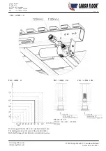
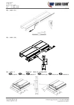
can simply be changed with these. You remove the cap out of channel PB (Allen key 12 mm) Figure 12A/B. After
this you screw the choke out of the channel with allen key 12 mm. Screw the new (flow independent) choke in the
channel and fasten these by hand (about 50 Nm.). Screw the cap back into channel PB (allen key 12 mm.) and
fasten these by hand (about 50 Nm). Let the floor run (loading and unloading) in order to check if everything is
functioning well and no leakage occur. The flow independent choke has a flow range of 20-110 ltr./min. and is
suitable for a maximal work pressure of 225 bar.
For both types of chokes applies: connecting the pressure and return wrongly will result in a
malfunctioning of the system.
B- control
An other possibility to be independent from a variable oil flow is using a B-control. With this the
loading/unloading direction is determined by a handle.
D
ANSCHLUSS DER HYDRAULIK
Das Cargo Floor System ist standardmäßig mit einem vormontierten Druckfilter an der Bugbrücke versehen, sehe
Abb. 10. Vom Steuerventil zum Druckfilter ist eine hydraulische Druckleitung (20 x 2 mm) vormontiert. Der
Eingangskanal des Druckfilters ist mit einer ¾“ x 20 mm Einschraubkupplung versehen. Außerdem ist eine
hydraulische Rückleitung (25 x 2,5 mm) vom Steuerventil zur Bugbrücke vormontiert, sie endet mit einer geraden
Anschlusskupplung (25 - 25 mm). An die vorgenannten Kupplungen können bei Bedarf direkt Hydraulikschläuche
(nicht im Lieferumfang enthalten) angeschlossen werden (die mitgelieferten Drehringe und Schneideringe sind
dann überflüssig). Wenn an Stelle eines Hydraulikschlauchs ein Hydraulikrohr montiert werden soll, können Sie
die mitgelieferten Drehringe und Schneideringe verwenden.
Wichtig:
Vor dem Anschließen aller hydraulischen Komponenten müssen diese sorgfältig gereinigt sein, wobei
insbesondere darauf zu achten ist, dass keine Dichtkappen / Reinigungsstopfen zurückbleiben.
Versuchen Sie, möglichst wenige gebogene / winklige Kupplungen zu verwenden (Grund: Druckverlust bzw.
Aufbau des Rückstromdrucks).
Drossel:
Für die ordnungsgemäße Funktion des Steuerventils wurde eine Standard-Drossel in den PB Kanal des
Steuerventils montiert, die für einen Öldurchfluss von 80 bis 110 Liter/Minute ausgelegt ist. Bei einem
abweichenden Öldurchfluss kann die Funktion des Steuerblocks beeinträchtigt werden. Das Diagramm für den
Öldurchfluss (Abb. 11) zeigt an, welche Öffnung bei welchem Öldurchfluss angezeigt ist. Eine mögliche
Anpassung ist leicht durchzuführen, indem der Durchmesser der Drossel geändert wird.
Erkennbare Folgen eines falschen Drossel-Durchmessers sind:
-
zu geringer Öldurchfluss kein Schalten des Lade- und Entladeventils, der Boden kommt nicht in die
Ladeposition oder bleibt in der Ladeposition stehen;
-
zu hoher Öldurchfluss Geräusch- oder Lärmbildung im System, erhöhte Wärmeentwicklung und
kapazitätsverlust.

