background image

Cargo Floor B.V. 
P.O. Box 271 
7740 AG COEVORDEN 
The Netherlands 
Phone:   +31 (0)524-59 39 00 www.cargofloor.nl 
Fax:        +31 (0)524-59 39 99 

info@cargofloor.nl


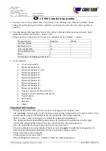
CF500 cylinder repair regulations, Article No. 9305003 


03-09-2008 / GB 7 of 26 
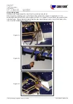
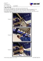
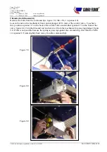
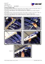
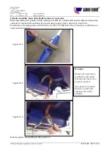


Remark/Warning: 
If the bolt on the back turns loose, but not the nut on the threaded rod, screw a bolt without a spacer in 
the mechanical pre steering plunger(Ø 16 mm, figure 10.0). Next, position a spanner 13 on the flat 
sides of the cartridge. The bolt ensures that the hollow shaft cannot be compressed when a spanner is 
positioned on the flat sides. 


Figure 10.0 

Summary of Contents for CF500 Power speed

Page 1: ...GB Repair regulations CF500 Cylinder disassembly ...

Page 2: ...19 Open end spanner 22 Open end spanner 24 Open end spanner 32 Open end spanner 36 Open end spanner 41 Open end spanner 46 Torque wrench 0 50 Nm with cap 13 Torque wrench 0 200 Nm with cap 24 Copper grease Steel brush Hammer Chisel Important information When possible draw in the cylinders to prevent damages to the cylinder rods The warranty will not apply if prior permission has not been obtained ...

Page 3: ...Phone 31 0 524 59 39 00 www cargofloor nl Fax 31 0 524 59 39 99 info cargofloor nl CF500 cylinder repair regulations Article No 9305003 03 09 2008 GB 3 of 26 Remove the plug caps from the coils of the GS02 on unload off and G02 load valves Use a 3 5 mm screwdriver ...

Page 4: ... Position an oil trough under the valve block to catch any leak off oil First loosen the coupling screw on the front of the control valve figure 1 0 spanners 32 36 Disassemble the pressure filter of the support 4 x M8 x 25 spanner 13 and remove the pressure filter with the P pipe Ensure that dirt cannot enter the pipe when putting it aside Cap off the outlet of the valve to avoid contamination fig...

Page 5: ...pipe disassembly Position an oil trough under the valve block to catch any leak off oil First loosen the coupling screw on the side of the control valve figure 4 0 spanners 41 46 Next loosen the bolts of the pipe bracket 2 x M6 x 40 spanner 10 and remove the pipe Ensure that dirt cannot enter the pipe when putting it aside Cap off the outlet of the valve to avoid contamination figure 6 0 Figure 4 ...

Page 6: ... spanner 10 Loosen the nut on the mechanical front control plunger Ø 16 mm of the control valve To achieve this position a spanner 17 on the back of the control valve and another spanner 17 on the front of the valve figure 8 0 Turn the threaded rod and remove it from the mechanical pre steering plunger figure 9 0 If this is not possible because the spring is pressing against the command lip first ...

Page 7: ...No 9305003 03 09 2008 GB 7 of 26 Remark Warning If the bolt on the back turns loose but not the nut on the threaded rod screw a bolt without a spacer in the mechanical pre steering plunger Ø 16 mm figure 10 0 Next position a spanner 13 on the flat sides of the cartridge The bolt ensures that the hollow shaft cannot be compressed when a spanner is positioned on the flat sides Figure 10 0 ...

Page 8: ...rtridge load First loosen the nut with which the coil has been mounted spanner 19 and remove the coil to ensure that the pins and the cartridge are not damaged figure 11 0 Next unscrew the cartridge from the control valve spanner 22 Seal the opening again using the GS021 plug which can be found next to the test connections in the block spanner 24 the code can be found on the valve figures 12 0 and...

Page 9: ...ylinder Cap off the A1 openings and the openings in the common rail Slightly loosen the coupling screw of pipe Q5 on the side of the control valve channel A1 spanner 32 36 leave the nut positioned but in such a way that the pipe can turn in the coupling Next loosen the nut on the side of the common rail rod side of the cylinder in such a way that it can be unscrewed immediately manually The pipe w...

Page 10: ... 7740 AG COEVORDEN The Netherlands Phone 31 0 524 59 39 00 www cargofloor nl Fax 31 0 524 59 39 99 info cargofloor nl CF500 cylinder repair regulations Article No 9305003 03 09 2008 GB 10 of 26 Figure 14 0 Figure 16 0 Figure 15 0 ...

Page 11: ...rod side of the cylinder You have to loosen the 12 M8 x 75 bolts spanner 13 figure 17 0 The common rail can now be removed Cover or cap off the channels of the common rail and of the cylinders to prevent dirt entering the system 18 0 Next disassemble the common rail at the bottom of the cylinder You have to loosen the 12 M8 x 75 bolts spanner 13 figure 19 0 The common rail can now be removed figur...

Page 12: ...GB 12 of 26 Cylinder disassembly note this should be done by 2 persons Hit back the vertical edge of the tab washers of the bolts M16 x 90 of the clamping plate on the bottom 2x of the triple clamping plate on the rod side 4x of the clamping plate located at the frame foot of the cylinder concerned 4x and of the rod guide set 2x Use a hammer and a chisel for this figures 22 0 and 23 0 Figure 22 0 ...

Page 13: ...13 of 26 The bolts of the triple clamping plate 4 x M16 x 90 can be unscrewed and removed figure 24 0 Next the bolts of the rod guide can be unscrewed and removed Now loosen the bolts of the single cylinder bottom figure 25 0 Do not remove these bolts yet but ensure that these can be unscrewed manually Next loosen the bolts of the clamping plate of the frame foot figure 26 0 Figure 25 0 Figure 24 ...

Page 14: ...03 09 2008 GB 14 of 26 Remove one clamping plate and loosen the other bolts in such a way that they can be removed manually Next 2 persons should grab the cylinder figure 27 0 you can also use a jack or a pit lift as an alternative and remove the last bolts and clamping sleeves The cylinder can now be removed figure 28 0 Remove the rod guiding by unscrewing the 2 M16 bolts Figure 27 0 Figure 28 0 ...

Page 15: ...n which the cylinder falls and the thread on the piston rod must be cleaned well and must be greased using copper grease figures 29 0 and 30 0 Position the 2 clamping plates with the bolts 4 x M16 x 90 that have the tab washers so that they are ready and within reach Slide the plastic rod guiding on the piston rod Figure 29 0 Figure 30 0 Figure 31 0 Warning Remove all caps before installation and ...

Page 16: ...f 26 Two persons should lift the cylinder and position it at the correct location Ensure that the thread is correctly positioned in the plate It must be positioned approximately in the centre of the supporting plate this is the sleeve that has been mounted on the frame foot figure 32 0 First mount a clamp around the piston rod at the frame foot and tighten both bolts a few turns figure 32 0 Figure...

Page 17: ...ulations Article No 9305003 03 09 2008 GB 17 of 26 Next install the single clamping sleeve on the cylinder bottom and tighten both bolts a few turns figure 33 0 Now install the triple clamping plate and the rod guide Do not yet tighten the bolts Check whether the slit that is located in the sleeve around the piston rod is in a horizontal position figure 34 0 Figure 34 0 ...

Page 18: ...air regulations Article No 9305003 03 09 2008 GB 18 of 26 Install a trimmed tab washer under the bolt head of the single clamping plate Refer to figure 35 0 Turn over the protruding tab and hit one side of the ring against the surface of the hexagon head bolt refer to figure 36 0 Remove all caps from the cylinders and from the common rail Figure 35 0 Figure 36 0 ...

Page 19: ...ossible in the sleeves by tightening the bolts but also ensure that the cylinder is not yet clamped Check whether the surfaces of the common rail are all in parallel to each other You can use the common rail for this figure 37 0 Warning Check that the surfaces on which the common rail is being mounted are really clean and that all plugs have been removed If they are correctly positioned mount the ...

Page 20: ...r regulations Article No 9305003 03 09 2008 GB 20 of 26 To correct the position of the cylinder should this be necessary you can position a spanner 17 on the bolts of the cover of the cylinder and turn it Note Do not position a spanner on the hexagon plug next to the piston rod It is very easy to damage the piston rod should the spanner slip figure 39 0 Figure 39 0 ...

Page 21: ... Tighten the cylinder 6x and frame foot 4x bolts using 150 Nm spanner 24 Tighten the plastic guiding set 2x bolts using 100 Nm spanner 24 figures 40 0 and 41 0 Ensure that the bolt heads of the cylinder frame foot and rod guide fastenings are all positioned pointing towards the tap washer with their flat sides to ensure that the washer rests against the flat side Tighten the bolts of the common ra...

Page 22: ...be performed in the reverse order of the disassembly process Please ensure that all caps from the oil channels have been removed when carrying out the assembly Check that the channels are clean Use copper grease for the assembly in relation to the bolts Tighten the bolts 4 x M8 x 75 spanner 13 using 30 Nm Check whether the right choke is under the PB plug refer to the arrow in figure 17 0 on the b...

Page 23: ...ns Article No 9305003 03 09 2008 GB 23 of 26 If it has not been installed a choke must be installed You can transfer the choke from the disassembled block to the new block You can also install the new choke that has been supplied Ensure that the diameter of the hole agrees with the flow Refer to the diagram below to obtain information about the size Figure 45 0 Figure 46 0 PB ...

Page 24: ... should be positioned on the coil of the G02 cartridge Refer to figure 48 0 With the DEUTSCH connector the black plug should be used for the GS02 coil and the grey plug for the G02 coil Checking for leakage After the control valve is connected the threaded rod has to be mounted Before the threaded rod is adjusted the system has to be checked for leakage In order to do this the bolts behind the spr...

Page 25: ...ire rod is fastened securely to the switchover valve plunger see figure 33 If not then screw the wire rod 1 as far as possible into the plunger and secure this with the contra nut 2 spanner size 17 Loosen nuts 3 and 4 spanner size 17 and move these about 3 cm in the direction of the switchover valve Now switch the pump on The system will stop now at the point where the command lip no longer operat...

Page 26: ...ll under the guarantee then you must comply with a number of conditions The defective component must be returned to us by prepaid post A copy of the Cargo Floor packing slip for the new component must be included in the package This packing slip must include the following information the Cargo Floor system number the number of articles which are being returned with their associated article numbers...

Reviews: