background image

12

13

Vedpak 98UK_Version 5_010909

160775

GB

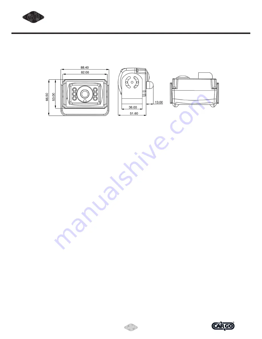
INSTALLATION FOR COLOUR CAMERA

INSTALLATION
With standard mounting bracket and fasteners included in 
the package, the camera can be mounted firmly 
at the required position of the vehicle.

1. Install the camera on the mounted camera bracket using
  proper fasteners (included in the package). 
  Decide direction for the camera to view when installing 
  the camera on the bracket.
2.  Run the built-in camera cable connection (1.5 mtr) to 
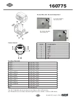
  monitor with camera extension cable 
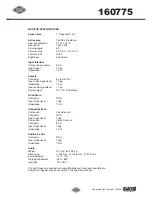
  (20 mtr. standard length included in the package) into the
  vehicle body (make a 13 mm. (½") hole on the vehicle 
  body if necessary). Connect the cable connectors firmly 

inside the vehicle with aid of a Loop-tie, and use weather 
sealer strip to help protect the cable connection. Seal the 
hole properly with weather sealant where the cable runs 
through vehicle body

3. For maximum weather protection, the cable connection is
  always recommended 

NOT to be left outside the vehicle. 

4. This device has the function of night viewing. In the dark, 

the IR will be enabled and the image is more clearly.

CONNECTION OF CAMERA 5

Connection of camera 5 is done using the adapter Cargo 
160603.


Yellow RCA jack to VIDEO IN.


White RCA jack to AUDIO IN.

Furthermore 

12 V / GND is connected to the camera via the 

red and black leads of the adapter.

CAUTION

1. Adjust the camera angle so that the rear bumper or the 

rear end of the vehicle is visible on the monitor (at the 
bottom brim of the view).

2. To prevent vibration, be sure to install the camera in a 

position at which it can be installed securely. Take the 
necessary measures for reinforcement if there is no place 
the camera can be installed  


securely.

3. 

Note that there will be blind spots if the camera is 
installed on the rear bumper, step, or in other low position. 
Avoid installing the camera in places where the lens can 
be easily get dirty from mud, exhaust gases, ect.

4. Be sure to waterproof the holes used to install the 

camera mounting bracket on the car, the bolts, and the 
cable holes.

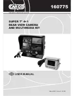
Summary of Contents for 160775

Page 1: ...GB 1 Automotive components since 1963 GB 160775 SUPER 7 4 1 REAR VIEW CAMERA AND MULTIMEDIA KIT USER MANUAL Vedpak 98UK_Version 5_010909...

Page 2: ...2 Vedpak 98UK_Version 5_010909 160775 GB...

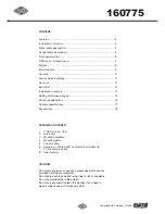
Page 3: ...pecifications 15 Camera specifications 17 Accessories 18 PACKAGE CONTENTS 1 7 LED monitor 16 9 2 Sun hood 3 Mounting brackets 4 Mounting parts 5 Control cable 6 Camera w infrared LED s and built in mi...

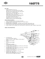
Page 4: ...able viewing angle before tightening the screws 5 Connect the control cable to the power socket which is located at the rear side of the monitor 6 Monitor installation is now completed Each control ca...

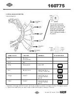
Page 5: ...direction light L ON SCREEN VIEW 1 Activation of the trigger cables for reverse right or left overrides any selection of images and shows the triggered camera 2 When pull the hand break user need to...

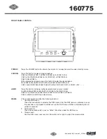
Page 6: ...AM R AV JUMP Press this button to display defined camera input user can select QUAD SEQ CAM A B CAM C R CAM A R CAM R B CAM A C CAM C B CAM R AB CAM R AB CAM A CAM B CAM C CAM R via OSD as default val...

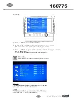
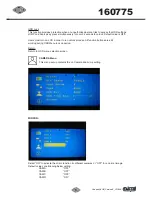
Page 7: ...lour of the content turns from yellow to red to enter system settings Turn the MENU button left or right to adjust your setting value DISPLAY OSD DISPLAY CAMERA RECALL EXIT SCREEN Menu This menu set u...

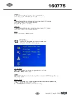
Page 8: ...ing value from 0 100 Default value is 50 Return Return to OSD menu selection screen DISPLAY Menu This menu set up contains the on screen identification and the activation of the distance gauge Auto Da...

Page 9: ...lue is OFF Users must turn on LCD in order to run unlock process All function buttons are still working during OSD Menu lock up period Return Return to OSD menu selection screen CAMERA Menu This menu...

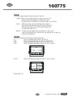
Page 10: ...en will show dual image for both rear and left hand side view SINGLE Screen shows only single picture on direction turn The screen will show only left side view on left turn and only right side view o...

Page 11: ...le pressing the JUMP button and press again to return the default screen CAM R B Obtain image from camera R B in dual picture while pressing the JUMP button and press again to return the default scree...

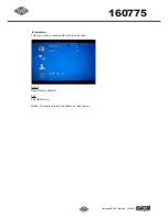
Page 12: ...12 Vedpak 98UK_Version 5_010909 160775 GB Information This menu set up contains Recall Exit function Recall Recall factory default Exit Exit OSD menu Notice Firmware version has shown on last column...

Page 13: ...tion is always recommended NOT to be left outside the vehicle 4 This device has the function of night viewing In the dark the IR will be enabled and the image is more clearly CONNECTION OF CAMERA 5 Co...

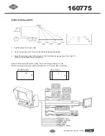
Page 14: ...ance behind the vehicle 3 Adjust the viewing angle of the camera so that the distance gauge shown from the TFT match to the distance behind the vehicle Switch to Rear view with source button the scree...

Page 15: ...t audio signal level 1 Vpp Power output DC 12 V 350 mAmp AV Audio In Connector RCA Input signal level 1Vpp Impedance 1 KW Output Interface Composite Life video out Connector RCA Input signal level 1Vp...

Page 16: ...Cam B Audio from Cam B Cam C Audio from Cam C Cam R Audio from Cam R Cam A Cam B Audio from Cam A Cam C Cam R Audio from Cam R Cam A Cam R Audio from Cam R Cam R Cam B Audio from Cam R Cam A Cam C Au...

Page 17: ...lumination 0 Lux F2 0 w IR LED ON Video Output Composite 1 0 Vp p 75 ohm Automatic Gain Control ON Aperture Correction Yes Frequency Horizontal NTSC 15 734 KHz PAL 15 625 Khz Frequency Vertical NTSC 5...

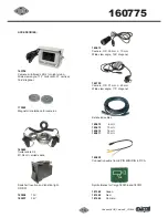
Page 18: ...it W 3 5 mtr coiled cable Switch w location and function light on off 180206 12 V 180207 24 V 160610 Camera O D 30 mm L 70 mm Wide view angle 130 diagonal 160790 Camera O D 21 mm L 40 mm Wide view ang...

Page 19: ...19 Vedpak 98UK_Version 5_010909 160775 GB...

Page 20: ...Automotive components since 1963 Vedpak 98UK_Version 5_010909 160775...

Reviews: