16
❏
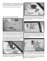
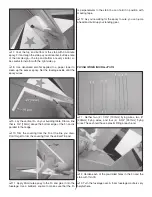
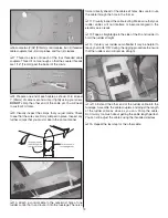
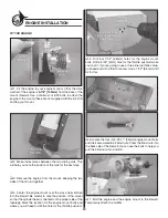
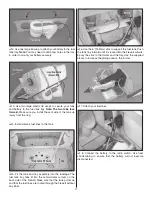
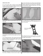
3. Connect your servo leads and the battery switch lead to
the receiver. Connect a Y-harness to your aileron channel. Wrap
the receiver in latex foam rubber and install it in the fuselage.
❏
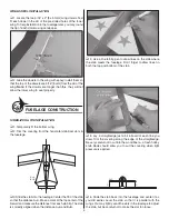
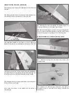
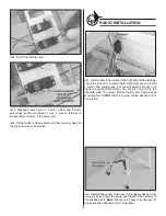
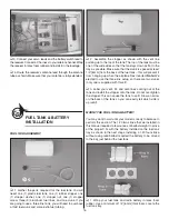
4. Route the receiver’s antenna lead through the antenna
tube as shown. Make sure that your antenna is fully extended.
FUEL TANK & BATTERY
INSTALLATION
FUEL TANK ASSEMBLY
❏
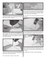
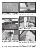
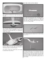
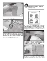
1. Gather the parts required for the fuel tank. You will
need: one (1) plastic fuel tank, one (1) rubber stopper, one
(1) stopper washer, one (1) stopper nut, one (1) stopper
screw, three (3) aluminum fuel lines, and one clunk. If you
are going to use a three line tank, you will need to purchase
a third fuel clunk and some extra fuel tubing.
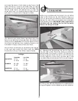
❏
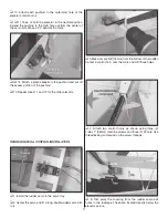
2. Assemble the stopper as shown with the vent line
pointing up to the top of the tank. The top of the tank must be
one of the wide sides so that the tank lays down as fl at to the
tray as possible. Make sure that the clunk is spaced at least
1/4" [6mm] from the back of the fuel tank – this will prevent it
from hanging up when the airplane fl ies inverted.
Note:
We
elected to use the three line setup, so there are two clunks
(only one is supplied with this kit).
❏
3. Label your vent, fi ll, and carb lines coming out of the
tank and install the stopper onto the tank. Do not overtighten
the stopper: this can cause the tank to split. Draw an arrow
on the back of the tank so you can easily tell which side is
up (vent).
MOUNT THE FUEL TANK & BATTERY
You may want to wait until your model is ready to balance to
perform this section. The 1.20 two-stroke that we installed in
this manual required a few ounces of ballast weight to arrive
at the proper C.G. with the battery installed on the fuel tank
tray as shown in the next steps. Installing a 1.20 four-stroke
without using lead ballast required the battery to be moved
to the bay just behind the fuel tank.
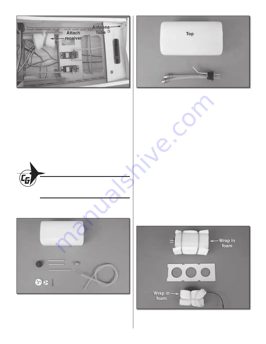
❏
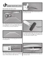
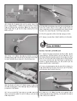
1. Wrap your fuel tank and radio battery in latex foam
rubber. Use a minimum of 1/4" [6mm] thick foam. Locate the
fuel tank tray.


