❏ ❏
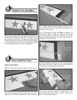
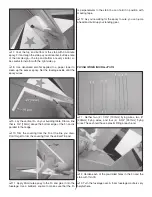
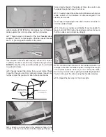
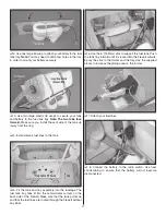
6. Hold the aileron in its full defl ected position as you’re
pushing in and apply 10 to 12 drops of thin CA to each hinge. Turn
the wing over and apply CA to the opposite side of the hinges.
❏
7.
Repeat steps 4 through 6 for the other ailerons.
SERVO & CONTROL HORN INSTALLATION
❏
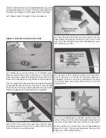
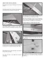
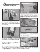
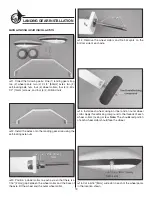
1. Gather four (4) servos and four (4) 12" [305mm] servo
extension leads. Attach a lead to each servo. To secure the
leads, use a piece of heat shrink tubing over the connection OR
place a drop of medium CA along the seam of the connection.
❏
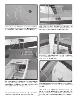
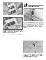
2. Tie a guide string to the end of each servo lead and carefully
pull the lead through the wing. You may have to move the lead
back and forth in the wing in order to clear each rib, so be careful.
Save your guide strings for the elevator servo installation.
❏
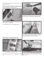
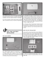
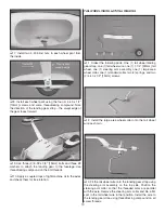
3. Position the servos in the servo bays with the output
shaft facing forward. Using a 1/16" [1.6mm] drill bit, drill the
holes for the servo mounting screws.
❏
4. Use the screws that came with your servos to tap the
holes. Remove the screws and place a drop of thin CA into
each hole. This will harden the wood and will keep the screws
from loosening over time.
❏
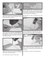
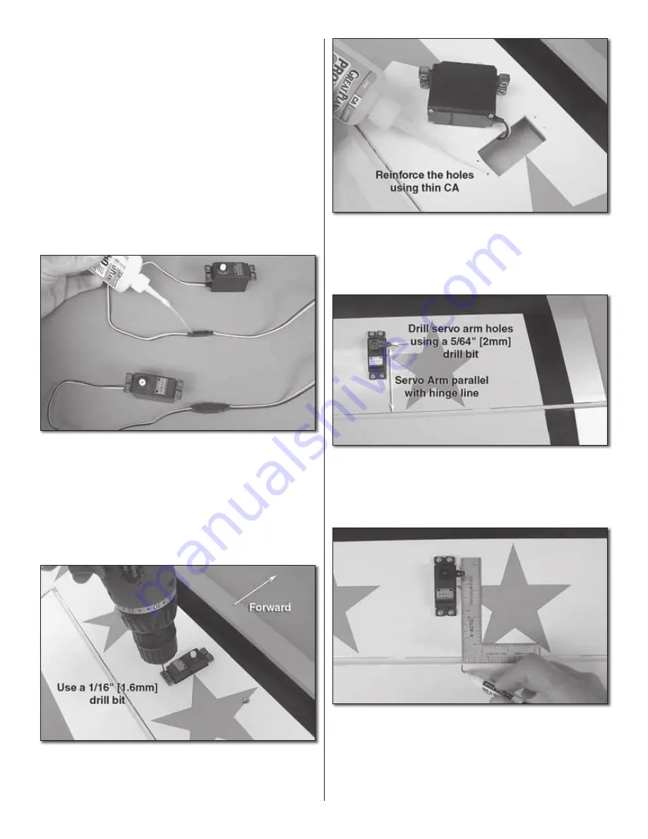
5. Use your radio to center your servos and install servo
arms on each servo so that the arm that faces outboard is
90 degrees to the servo case and is parallel with the hinge
line. Drill the holes with a 5/64" [2mm] drill bit. Cut off the
remaining arms.
❏
6. Use a straightedge or a builder’s square to mark the
position of the control horn centerline directly behind the third
hole out from the center of the servo. Do this for each aileron.
❏ ❏
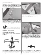
7. Locate four (4) control horns, four (4) backplates and
twelve (12) 2-56 x 1" [25mm] machine screws. Have your drill
ready with a 3/32" [2.4mm] drill bit.
4


