background image

19

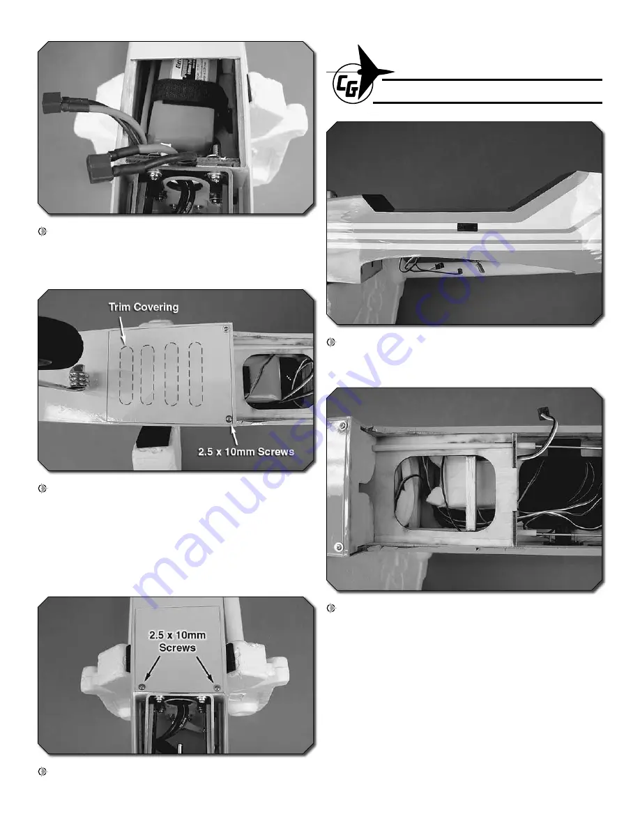
 5. Test fi t your battery packs in the battery compartment. 

They can be secured together with additional self-adhesive 
hook and loop material, but the packs may need to be 
inserted into the compartment one at a time.

 6. Fit the ESC hatch cover in place and drill through 

the pre-cut mounting holes into the hardwood rail using a 
1/16" [1.6mm] drill bit. Thread a 2.5x10mm washer head 
self-tapping screw into each hole and back it out. Apply a 
drop of thin CA to each hole to harden the wood. Install the 
hatch cover using two 2.5x10mm washer head self-tapping 
screws. Trim the covering from the cool air exit slots in the 
hatch cover.

 7. Mount the battery hatch cover using two 2.5x10mm 

washer head self-tapping screws.

FINISH THE MODEL

 1. Pre-cut slots are provided on both sides of the fuselage 

for an on/off switch. The slots may need to be enlarged 
depending on what brand switch harness you are using.

 2. Wrap your receiver and receiver battery in foam rubber 

(not included). Connect the battery to the switch and the 
servos and switch lead to the receiver (be sure to secure the 
connection between the battery and the switch using tape or 
heat shrink tubing). Stuff the components into the fuselage 
and use scrap sticks of wood to hold them securely in place. 
It is recommended to only tack glue the sticks in place at this 
time as the components may need to be shifted forward or 
aft when balancing the plane. When the exact position of the 
radio components is confi rmed, be sure to thoroughly glue 
the sticks in place.

Summary of Contents for Tiger 2 ARF

Page 1: ...r modify this warranty without notice In that Carl Goldberg has no control over the final assembly or material used for final assembly no liability shall be assumed nor accepted for any damage resulting from the use by the user of the final user assembled product By the act of using the user assembled product the user accepts all resulting liability If the buyer is not prepared to accept the liabilit...

Page 2: ...equire planning or decision making before starting to build Order numbers are provided in parentheses RADIO EQUIPMENT The Tiger 2 ARF requires a minimum 4 channel radio system with four 44 oz in 3 2 kg cm minimum standard servos If you are installing a glow engine an additional standard servo is required for the throttle In addition two 9 229mm servo extensions are required for the aileron servos ...

Page 3: ...RF Order numbers are provided in parentheses R C foam rubber 1 4 6mm HCAQ1000 3 900mm standard silicone fuel tubing GPMQ4131 Glow engine installation only ADHESIVES AND BUILDING SUPPLIES This is the list of Adhesives and Building Supplies that are required to finish the Tiger 2 ARF 1 2 oz 15g Thin Pro CA GPMR6001 Pro 30 minute epoxy GPMR6047 Masking tape TOPR8018 Threadlocker thread locking cement ...

Page 4: ... heat to tightenthecoveringifnecessary Applypressureoversheeted areas to thoroughly bond the covering to the wood BUILD THE WING PANELS INSTALL THE AILERONS Do the right wing first so your work matches the photos the first time through You can do one wing at a time or work on them together 1 Drill a 3 32 2 4mm hole 1 2 13mm deep into the center of each hinge slot in the aileron and wing panel Trim...

Page 5: ...n 5 Repeat steps 1 4 for the other wing panel INSTALL THE AILERON SERVOS AND PUSHRODS 1 Trim the covering from the aileron servo bay on the underside of the wing panel Cut off unused arms Enlarge to 5 64 2mm 2 Cut three arms from a four armed servo arm for the aileron servo Enlarge the outer hole of the remaining arm with a 5 64 2mm drill bit 3 Attach a 9 229mm servo extension to the aileron servo...

Page 6: ...in CA to each hole to harden the wood When the CA has dried install the servo using the hardware supplied with the servo 5 Thread a nylon clevis 20 complete turns onto a 6 152mm pushrod Slide a silicone clevis retainer onto the clevis and connect the clevis to the outer hole of a control horn Hinge Line Hinge Line CORRECT INCORRECT Hi 6 Position the control horn onto the aileron using the position...

Page 7: ...pe or a small clamp to hold the aileron in the neutral position Make a mark on the pushrod where it crosses the outer hole in the servo arm Make a 90 degree bend at the mark on the pushrod and cut off the excess pushrod 1 4 6mm beyond the bend Attach the pushrod to the servo arm using a 90 degree pushrod connector Thread the clevis up or down on the pushrod as necessary to center the aileron with ...

Page 8: ...ibs if necessary to achieve the correct fit The root ribs should join together tightly with no gaps When satisfied glue the anti rotation pin halfway into the hole of one of the wing panels as shown 3 Use a mixing stick or something similar to coat the inside of the wing joiner pockets of both wing panels with 30 minute epoxy Thoroughly coat one half of the wing joiner with 30 minute epoxy and inser...

Page 9: ...n at a rate that will just melt the covering and not burn into the wood The hotter the soldering iron the faster it must travel to melt a fine cut Peel off the covering INSTALL THE MAIN LANDING GEAR 1 Slide a 4mm wheel collar onto each main landing gear wire followed by a wheel and another 4mm wheel collar Center the wheels on the landing gear wires and mark the position of the wheel collars onto t...

Page 10: ...to the fuselage using two 4x25mm machine screws and two 4mm flat washers The wing will be used to properly align the horizontal stabilizer onto the fuse 2 Place the horizontal stab onto the stab saddle as shown Center the stab left and right on the fuse making a center mark on the stab is helpful and make the distance between wing and stab tips equal on both sides When satisfied use a felt tip pen t...

Page 11: ...When satisfied test fit both elevator halves onto the joiner wire and lay them on a flat surface If both elevator halves do not lay flat tweak or bend the joiner wire until they do Do not attempt to bend the joiner wire with it inside the elevators 7 Roughen the ends of the joiner wire with 220 grit sandpaper and clean them off with alcohol As you did with the ailerons dry fit the elevator halves onto ...

Page 12: ...ape to hold the fin square while the epoxy cures 11 Trim the covering from the tail servo pushrod exits on the left and right sides of the fuselage Temporarily insert a 29 1 2 749mm pushrod into the elevator outer pushrod tube that exits the left side of the fuselage Use the position of the pushrod to mark the location for the elevator control horn onto the underside of the elevator 12 Drill 5 64 2...

Page 13: ...be and connect the clevis to the third outer hole of the rudder control horn As you did with the aileron pushrods use tape or a small clamp to hold the rudder in the neutral position Make a mark on the pushrod where it crosses the outer hole in the servo arm Make a 90 degree bend at the mark on the pushrod and cut off the excess pushrod 1 4 6mm beyond the bend removing the pushrod from the fuselag...

Page 14: ... compound 4 Fit the nylon steering arm between the two nose gear bearing block halves Slide the nose gear wire up through the bearing blocks and the steering arm Square the axle of the nose gear wire with the length of the fuselage Rotate the steering arm so it is approximately 20 degrees to the firewall as shown Mark the location of the threaded hole in the steering arm onto the nose gear wire 5 R...

Page 15: ... motor If you plan to install a brushless motor skip this section as it only contains information relevant to installing a glow engine 1 The fuel tank can be assembled as a two line system consisting of a vent pressure line to the muffler and a carb line Filling and emptying of the tank would need to be done through the carb line or an optional fuel fill valve not included The tank can also be assem...

Page 16: ...tank with additional foam rubber The tank should be held securely by the foam rubber Fit the fuel tank hatch cover in place and drill two 1 16 1 6mm pilot holes through the forward end of the hatch cover and into the firewall Thread a 2 5x10mm washer head self tapping screw into each hole and back it out Apply a drop of thin CA to each hole to harden the wood Install the hatch cover using two 2 5x1...

Page 17: ...ed in the fuse Fit the aft end through the screw lock pushrod connector installed on the throttle servo Make any necessary bends to the forward end of the pushrod and connect the clevis to the throttle arm on the carburetor Adjust the pushrod in the screw lock connector so the servo properly opens and closes the carburetor When satisfied tighten the screw lock connector screw slide the silicone cle...

Page 18: ...washer to draw four 4mm blind nuts tight into the holes Attach the motor mount to the firewall using four 4x20mm machine screws four 4mm flat washers and thread locking compound 3 Apply a thin coating of epoxy where you plan to mount the ESC This will improve the adhesion of the double sided foam mounting tape not included Let the epoxy cure undisturbed Connect the ESC to the motor This is a good ti...

Page 19: ... cover using two 2 5x10mm washer head self tapping screws FINISH THE MODEL 1 Pre cut slots are provided on both sides of the fuselage for an on off switch The slots may need to be enlarged depending on what brand switch harness you are using 2 Wrap your receiver and receiver battery in foam rubber not included Connect the battery to the switch and the servos and switch lead to the receiver be sure...

Page 20: ...nd peel off the paper backing Note Even though the decals have a sticky back and are not the water transfer type submersing them in soap water allows accurate positioning and reduces air bubbles underneath 3 Position decal on the model where desired Holding the decal down use a paper towel to wipe most of the water away 4 Use a piece of soft balsa or something similar to squeegee remaining water f...

Page 21: ...EVER charge at currents greater than 1C ALWAYS set charger s output volts to match battery volts ALWAYS charge in a fireproof location NEVER trickle charge NEVER allow battery temperature to exceed 150 F 65 C NEVER disassemble or modify pack wiring in any way or puncture cells NEVER discharge below 3 0V per cell NEVER place on combustible materials or leave unattended during charge or discharge ALW...

Page 22: ...fter you have become accustomed to the way the Tiger 2 flies you would like to change the throws to suit your taste that is fine However too much control throw could make the model difficult to control so remember more is not always better BALANCE THE MODEL C G More than any other factor the C G balance point can have the greatest effect on how a model flies and may determine whether or not your first ...

Page 23: ...is heavy Balance the airplane by adding weight to the other wing tip An airplane that has been laterally balanced will track better in loops and other maneuvers FLYING The Tiger 2 ARF is a great flying model that flies smoothly and predictably The Tiger 2 does not however possess the self recovery characteristics of a primary R C trainer and should be flown only by experienced R C pilots FUEL MIXTURE...

Page 24: ...24 Copyright 2009 GBGA1066Mnl www carlgoldbergproducts com ...

Reviews: