12.
!
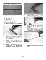
When the bent tip is exiting the hole in the
pushrod and the plug tightly meets the
pushrod, apply CA glue to the joint.
13.
!
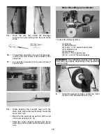
Insert both of the nylon guide tubes into the
exit holes located closest to the stab on
each side of the model.
11.
!
Place the single-hole plug onto the wire and
then bend the wire, as shown.
!
Referring to the drawing, cut the wire after the
bend and slide the end of the wire into the
single-hole end of the pushrod.
8.
!
With the pointed end of the plug facing the
threaded end of the wired, slide the double-
hole plug onto the non-threaded end of the
wires.
!
Measure 2-3/8” down from the second bend
and make a 90º bend. Then, cut the wire
after the bend, so that it will fit in the
pushrod.
9.
!
Insert the two wires into the double-hole end
of the pushrod until the bent ends slide into
the holes.
!
Slide the plug as far as it will go down into
the pushrod. Then, use medium CA to glue
the plug to the pushrod.
10.
!
Using Drawing #2 as a template, mark the
location of the bend on the third threaded
wire.
14.
!
When the nylon tubes have been pushed
through the fuselage, insert the two wires
from the end of the pushrod into the tubes.
!
At this time place snap-r-keeper on the servo
end of the pushrod. Push the snap-r-keeper
towards the fiberglass pushrod. You will
mount the keeper to the servo arm later.
!
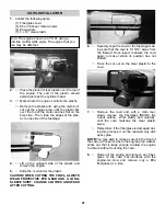
Then, slide the pushrod back down through
the fuselage, allowing the nylon tubes to
guide the way until the two ends of the
pushrod come out of the exit holes on either
side of the airplane.
15
Summary of Contents for decathlon arf
Page 29: ......

