4
INTRODUCTION
USING THIS INSTRUCTION MANUAL
Before you start gluing and sanding, take some time
becoming familiar with the plans and looking through this entire
instruction booklet. It is designed to guide you through the con-
struction process step by step, so build in the order given in this
book. Balancing, setting up and flying the model are also cov-
ered.
Like a full-size airplane, the
EAGLE II
is built from
basic structures (stabilizer, fin, wing, etc.), which are then
assembled into the complete airplane. Special procedures or
comments will usually be explained before a step, so you will be
prepared. If a step begins with a statement like “Note,”
“Warning,” or “Important,” it is a good idea to read through the
step before doing it.
A check-off box appears at the beginning of each step.
Check these boxes as you build, so you can tell at a glance
what steps you have completed. Some steps are repeated and
must be marked twice, as in the case of the left and right wing
panel.
HOW TO READ THE PLAN
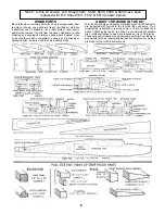
There is one plan sheet in this kit, showing the
Fuselage (Body), the Wing, and the Tail Parts. Everything on
the plan is drawn to full-size and shape and shows how the fin-
ished parts fit together.
The plan is drawn to show the model completely
assembled, but as a result, the areas inside or underneath are
covered up, making it hard to understand how these parts fit
together. Therefore, for clarity, some parts are drawn with hid-
den lines, others with breakaway views, and some are entirely
removed from the structure and shown separately.
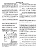
For example, on the fuselage, the left side of the com-
pleted model has been removed to show the details inside.
Sometimes a surface is broken away to reveal the detail behind
or underneath. Dashed lines indicate details that are hidden
behind or under another part of the surface.
FUSELAGE DRAWN WITH LEFT
SIDE REMOVED TO REVEAL
INNER FUSELAGE DETAILS
THE WING IS SHOWN CUT
THROUGH AT THE CENTER-
THIS IS A “SECTION” VIEW
Dashed lines show
a part “Hidden
behind the fuel tank.
Fuselage side “Breakaway” view
to show how switch is mounted
The model is made from four varieties of wood: balsa,
bass, birch, and various plywoods. Each kind of wood has its
own characteristic
end grain pattern
(as viewed from the end)
which has been drawn on the plan. You can easily use these
end grain patterns to identify what kind of wood is shown for
that part, if you are in doubt.
HOW TO USE THE PLAN
The plan is used in several ways. The wings, stabilizer,
and fin are assembled directly over the plan. Each wood part is
matched over its corresponding location printed on the plan and
pinned in place. To prevent ruining your plan from gluing your
wings, etc. to it, cover the area you are working on with waxed
paper.
The paper the plan is printed on can expand or contract
slightly with changes in temperature or humidity. Because of this, a
preformed part such as the notched wing trailing edge may not
exactly match the plan. This is no problem, as slight deviations in
the outline or size will not noticeably affect flight performance.
Because the fuselage plugs together and is self-aligning,
it is not built directly over the plan. As you assemble the fuselage,
you will find the plan helpful in identifying parts and how things fit
together.
The plan also shows the installation of a typical radio, battery and
all remaining equipment and hardware needed to complete the
model. By referring to the examples shown, you should be able to
install your own radio, etc., even if it is not the same as what is
shown on the plan.
IDENTIFYING PARTS
Parts for the wing are bundled together; likewise, parts for the tail
assembly are also grouped. Die-cut plywood and balsa sheets of
common sizes are bundled together, so they are less likely to be
damaged during shipping and handling. The various screws,
hinges, and fittings are packaged in plastic bags.
PREPARING FOR ASSEMBLY
Set a flat, warp-free pinning board on your work bench. Any mate-
rial that accepts pins, such as insulation board, soft plywood, or dry-
wall (sheet rock) will work. Important: any warps or bends in the pin-
ning board will result in wings or tail surfaces that are also warped
or bent, making your model more difficult to fly. Make sure that the
pinning board is flat by laying a straight edge across it. You may be
able to correct a warped board by shimming its low areas.
Position the area of the plan (such as the stabilizer) on which you
are going to build over the pinning board and tape it in place so the
plan lays flat and wrinkle free.
Place a sheet of waxed paper over the work area to prevent
SUPER JET from sticking to your plan and ruining it.
CONSTRUCTION TIPS
In assembling your model, the following tips will prove helpful.
IMPORTANT: ALWAYS READ A FEW STEPS AHEAD. This will
alert you to coming instructions and will help you plan accordingly.
You may find it convenient to empty all of the small parts
from the hardware bags into a common container, such as a mar-
garine tub. This will help you find items quickly.
Punch out only the die-cut (D/C) parts you need as you
proceed. This will help you keep track of parts, especially the small
ones.
After completing each section of the aircraft, you may want
to go back and re-glue the joints, just in case some area has been
missed. Be careful not to use too little glue, which will leave the
model weak, or too much glue, which can make the model heavy.
Properly glued joints are important to the overall strength of the
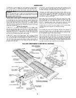
model. SUPER JET™ is recommended for most parts of the
assembly, although JET Epoxy may be used when more time is
needed for careful placement.
Summary of Contents for Eagle 2
Page 28: ...27 ...

