10.
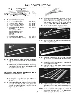
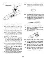
With the die-cut slot on the left side (as the pilot
faces the front) of the model, and engaging the
fuse notches with the sheeting taps, position the
top sheeting on the fuse. Glue in place.
Position the stab platform at the rear of the fuse,
between the fuse sides. Glue in place.
When the entire fuse assembly is completely dry,
remove all pins.
11.
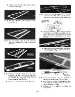
Apply a piece of electrical tape along the die-cut
centerline of the wing platform. Bend gently
along the centerline, until the wing platform
matches the dihedral angle on the top of
Formers “B” and “C.”
Position the wing platform between the fuse
sides and glue in place. Remove tape and apply
glue to the center area.
12.
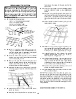
Take Former “A” and, ONLY IF USING A
GEARED MOTOR, remove the lower portion of
the cut-out. Refer to plan.
Position the former with the side stamped “R”
facing forward on the right side of the model, as
shown.
Glue Former “A” in place and allow to dry.
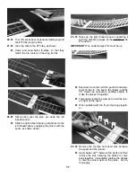
Spread the fuse front apart and, with the
dou-
bler strips facing toward the front
of the
model, plug Former “B” into the holes in the
fuse sides.
Now, with the doubler strips facing thr rear of
the plane, insert Former “C”.
NOTE: The v-cut tops of the formers face in toward
each other.
9.
Working over the plan, pin the balsa bottom
rear sheet in position.
Spread the fuse sides slightly apart and posi-
tion them over the rear bottom sheet, taking
care to engage the notches in the fuse sides
with the tabs in the bottom sheet. Remove the
rubber band on the tail.
Hold the sides in place on the bottom sheet by
pinning from the outside. Apply pins only in the
area 2” behind Former “C” to the rear of the the
fuse.
Remove the pins on the inside (holding down
the fuse bottom).
Insert Former “D” at locations previously
marked on fuse sides.
Thoroughly glue all of the joints attaching
Formers “B”, “C”, and “D” to the fuse bottom
and to the fuse sides. Allow to dry.
22
STAB
PLATFORM
POSITION SLOT
ON LEFT SIDE
APPLY GLUE ONLY IN THIS
AREA
REMOVE FOR GEARED MOTOS ONLY


