background image

3

Using This Instruction Manual 

Before you start gluing take some time to look through this entire

instruction booklet. It is designed to guide you through the con-

struction process step by step, so build in the order given in this

book. Radio selection and installation, covering, and balancing

and flying the model are all covered. 

Like a full-size airplane, the Gentle Lady is built from basic

structures (stabilizer, fin, wing, etc.), which are then assembled

into the complete airplane.

Special procedures or comments will usually be explained before

a step, so you will be prepared. If a step begins with a statement
like “Note,” “Warning,” or “Important,” it is a good idea to read
through the step before doing it. 

A check-off box appears at the beginning of each step. Check

these boxes as you build, so you can tell at a glance what steps you

have completed. 

Some of the instructions deal with general procedures. Boxes are

not needed for these sections.

Preparing For Assembly 

You will need a area approximatly 18” x 36” in order to build the

Gentle Lady ARF.

Place a sheet of waxed paper or plastic

kitchen wrap over the work area to prevent CA from sticking to
your table. 

Construction Tips 

If you have never assembled a built-up model before, the follow-

ing tips will prove helpful.

IMPORTANT: ALWAYS READ A FEW STEPS AHEAD. This

will alert you to coming instructions and will help you plan
accordingly. 

You may find it convenient to empty all of the small parts from

the hardware bags into a common container, such as a margarine
tub. This will help you find items quickly. 

When drilling any 1/16” holes in balsa, you may find it easier to

twist the drill between your thumb and index finger. This proce-
dure allows more control in positioning the drill on the center
mark. 

Parts Identification

Nose Block

Hatch

Stabilizer

Left Wing Panel

Fin 

Fuselage

Rudder

Right Wing Panel

Elevator

Additional Items included in the kit:

(2) Control Horns
(2) Control Horn Bases
(4) 2-56 x 1/2” Pan Head Screw
(2) Wire
(2) Snap Links
(2) Snap Link Retainers
(2) Pushrod Connectors
(1) Wood wing Joiner

Wing Assembly

1.

Collect the following parts:

(1) Left wing panel

(1) Right wing panel

(1) Wing Joiner

2.

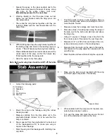
Holding the wing joiner with the angle cut facing up,

insert them into the joiner pockets in both wing

halves. The joiners should fit easily in the pockets

and the wing halves should meet in the middle, with

the wing dihedral forming a broad "V".

3.

Working on a protected surface, and with a paper

towel handy for cleaning fingers, 

THOROUGHLY

mix 1-2 large (soup) spoons each from bottle A and

bottle B of epoxy

.

(Use equal amount of each part

and mix with a stick in a plastic or paper cup, or on

a sheet of waxed paper.)

Summary of Contents for Gentle Lady ARF

Page 1: ...lplane was designed to be a gentle trainer for the beginning R C modeler yet to possess competition capability in the hands of the experienced glider pilot As a very efficient machine she reacts quickly to rising air called lift or thermals To stay in the thermal she can circle very tightly without falling off The model has good penetration into the wind and can really cruise when desired Before s...

Page 2: ...ur needs and skill level And be sure to get a system designed for aircraft as only certain fre quencies are available for model aircraft Necessary Tools and Supplies Roll of waxed Paper Modeling Knife and Single Edge Razor Blade Pins Electric Drill 1 16 Drill Bit Small Screwdriver Masking Tape Flexible Straight Edge 30 60 Degree x 6 Triangle Pencil Limited Warranty Carl Goldberg Products takes pri...

Page 3: ... the follow ing tips will prove helpful IMPORTANT ALWAYS READ A FEW STEPS AHEAD This will alert you to coming instructions and will help you plan accordingly You may find it convenient to empty all of the small parts from the hardware bags into a common container such as a margarine tub This will help you find items quickly When drilling any 1 16 holes in balsa you may find it easier to twist the ...

Page 4: ...l they are touching Make sure the rear dowel slides into the dowel hole 5 With masking tape tape the wing halves together at the trailing edge and close to the leading edge as shown This will help keep the wing from twisting Place additional tape at several locations across the center seam of the wing so that the halves stay firmly together while the epoxy sets Allow the epoxy to dry thoroughly No...

Page 5: ...m of the rudder Mark the holes Drill the holes for the control horn Again using two machine screws secure the control horn to the rudder 4 Place the control horn on the bottom of the elevator over the center mark you made Mark the screw hole locations Drill the holes for the control horn Using two machine screws secure the control horn to the elevator Remove the rudder from the fin and set to the ...

Page 6: ... tube 3 Insert the hinges into the slots of the fin Hint Place a pin in the center of the hinge so that the hinge will insert half way into the fin and the rud der When satisfied with the fit then place one drop of thin CA glue on each side of all the hinges Remove the pins and set aside for about 10 min utes Repeat this process for the elevator DO NOT FOR GET THE WIRE Nose 1 Mount your servos as ...

Page 7: ...cut through the side of the fuselage and mount your receiver switch as shown Plug the switch into the receiver as shown in your radio instructions Wrap the receiver and the battery pack in foam and place in the nose Plug the battery into the switch Take off the servo arms from that top of the servos then remove the masking tape from the rudder and the elevator Turn on the radio and let the servos ...

Page 8: ... Glue the nose cone on the front of the fuselage Make sure the you mount the nose cone on the cor rect way 1 Center the engine on the firewall doubler Mark engine hole mounting locations mix up some epoxy and place some onto the fire wall doubler Hold the firewall onto the fuselage with masking tape till the epoxy has dried 2 When the epoxy dries drill 1 16 holes at the marks for the engine mounti...

Page 9: ...teries fully charged turn on receiver and transmitter and actuate all controls many times until you are satisfied with all functions Prior to the beginning of each day s flying make a range check of your equipment in accordance with the manufacturer s instructions in general with antenna collapsed you should have at least 100 feet range on the ground To check this set the model facing away from yo...

Page 10: ... at the field is flying or testing on the same fre quency After the range check stand behind the model and make sure the control responses are correct Moving the control stick to the right should give right rudder on a 3 channel set up Moving the stick back or down on the Tx should move the elevator up and vice versa Finally make sure that everything on your aircraft is neatly and firmly in place ...

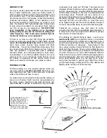
Page 11: ...ons can be gener ated fairly regularly It is appears that the time between the hours of 10 00 a m and 2 00 p m when the sun is at its highest angle are the most productive Keep all of this in mind while flying at your particular flying site Thermals can achieve very fast rates of climb Coupling this fact with the potentially large diameter it is easy to see how one might find it difficult to escap...

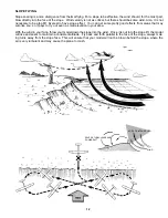
Page 12: ... areas that may surprise you so it pays to try out even a small elevation in your area With the wind in your face throw your model down the slope into the wind Once it is out into the slope lift the model will rise and seem to maintain a consistent altitude Fly back and forth parallel to the face of the slope always mak ing turns away from the slope face This will ensure that your model will not b...

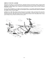
Page 13: ...ur model for better wind penetration If so add the weight perhaps starting with 6 8 ounces at the center of gravity making sure the weight is securely attached inside the model Loose ballanst can destroy a modle in rough conditions Landings can be a little tricky at first but with experience can be mastered Make your approach from either side keeping the nose of the model parallel to the wind Brin...

Page 14: ......

Reviews: