background image

13

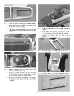
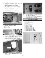
3.

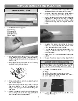
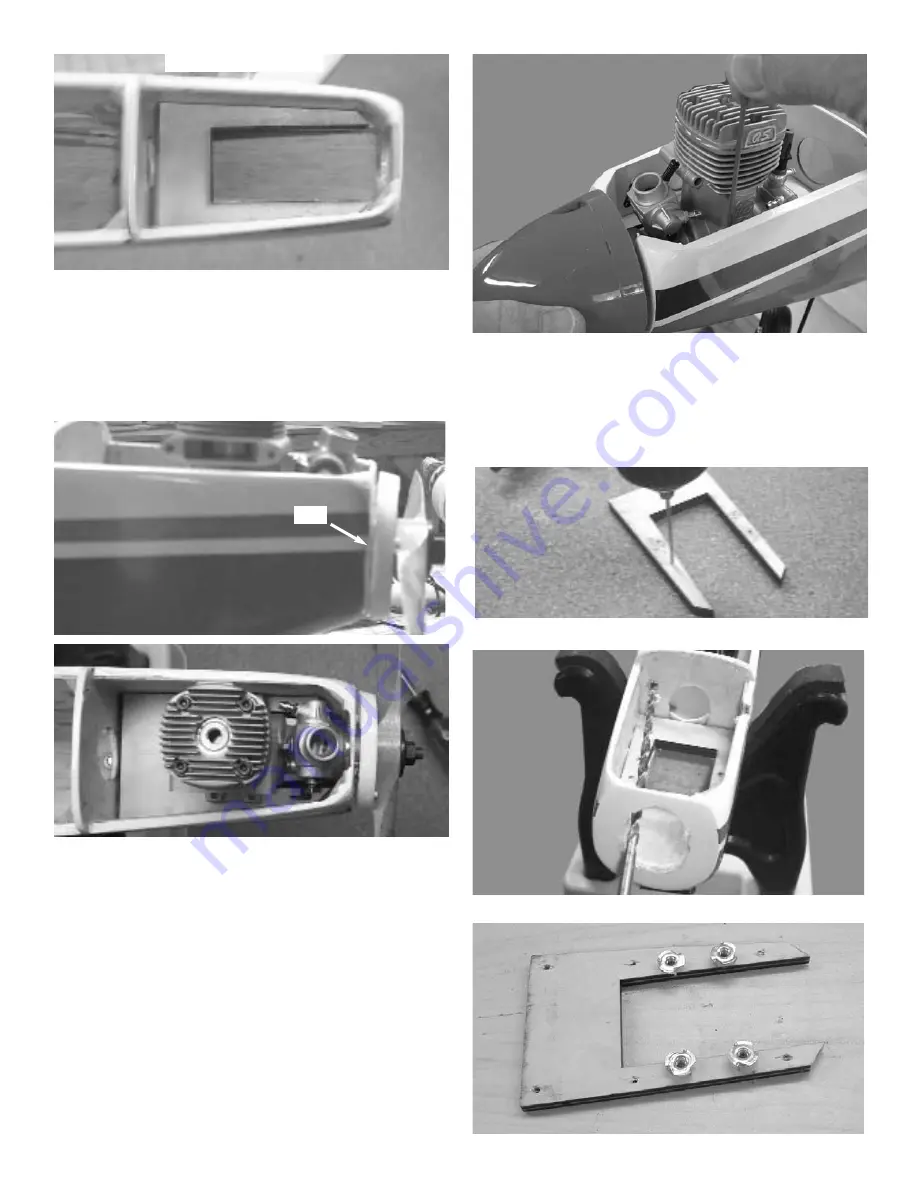
Place the mount into the front of the fuselage.

Make sure that the smaller side beam is on

the left side of the fuselage.

The motor mount should point a little to the

right about 2 degrees. Mark the top of the

plate.

Left side of the fuselage

Gap

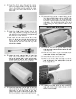
4.

Slide the engine into the motor mount and

through the front nose ring.

Open the spinner and place the spinner back

plate onto the engine. This will help to center

the front of the engine to the fuselage

Make sure that there is a clearance between

the spinner back plate and the front of the

fuselage .

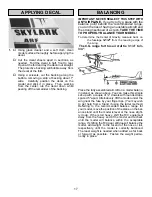
4.

Mark the location of the engine mounting

holes.

Also at this time mark the location of where

the throttle pushrod should exit the firewall.

Remove the engine and the motor mount

plate.

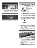
5.

Drill the engine mounting holes in the plate.

6.

Drill the hole for the engine throttle pushrod.

Summary of Contents for Skylark 70 ARF

Page 1: ... to immediately request a replacement of any parts he believes to be defective for their intended use The company warrants replacement of any such components provided the buyer requests such replacement with in a period of 90 days from the date of purchase and provided the defective part is returned if so requested by the company No other warranty expressed or implied is made by the company with r...

Page 2: ...TECHNIQUES CA adhesives are specially formulated to firmly glue the plywood hardwood and balsa used in your model and to withstand the vibration and stresses of high performance flight However there are times such as when you are installing the stabilizer and fin on the fuselage and want more set up time for careful alignment and positioning then you should use epoxy Occasionally you also will wan...

Page 3: ...ecommended by the manufacturer as indicated below under Check Ups SERVOS Servos are vibration prone Be sure to mount them with grommet shock mounts in servo trays which are also shock mounted Also be sure to keep them clean If the neutral position drifts this is a sign of change which should not be ignored find out WHY before flying again BATTERIES Nicads also can suffer from vibration so they too...

Page 4: ... wing 4 Carefully check the alignment of the aileron There should be about 1 32 on both ends When satisfied with the alignment remove the straight pins being sure to keep the aileron tight to the wing You may wish to apply a few pieces of masking tape to keep the pieces in place 5 Keeping the aileron and wing in position apply 3 or 4 drops of Ultra Set thin CA to the small exposed area of each hin...

Page 5: ...enter of the wing and the ser vos are installed in the wing Aileron AILERON CONTROL HORN INSTALLATION 1 Collect the following items 2 Large control horn with back plate 4 3 4 screw 2 Metal metal clevis 2 10 threaded rod 2 Swivel keepers 2 With the aileron servo arm in place make a mark at a 90º degree angle to the trailing edge and in line with the servo arm 1 5mm x 20mm MACHINE SCREWS METAL CLEVI...

Page 6: ...w 2 Locate the landing gear slots in the bottom of the wing and remove the covering material Insert the shorter end of the gear into the hole in the bottom of the slot so that it points toward the center of the wing 3 Use two Metal straps and four screws on each side to secure the wire gear 4 Install the wheels on the axles as shown First the wheel collar goes on followed by the wheel then the sec...

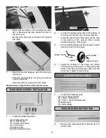
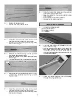
Page 7: ...he wood pushrod and push down into the groove Glue the wire to the wood pushrod using Ultra Set medium CA glue 8 Slide the heat shrink tubing over the pushrod and shrink using a blow drier Glue the tubing to the wood pushrod using thin CA glue This finishes the elevator pushrod Repeat for the rudder pushrod INSTALLING PUSHRODS 1 Collect the following parts 1 Elevator Pushrod 1 Rudder Pushrod 1 Fus...

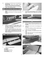
Page 8: ...de the wing saddle area 1 Slide the aluminum wing tube into one wing panel Slide the other panel on till the wings butt together STAB ELEVATOR INSTALLATION 1 Collect the following parts 1 Stabilizer 2 Elevator 1 Wing fuse assembly 6 CA hinges 1 Elevator joiner Wire 2 As with the wing and ailerons use a modeling knife to make sure the hinge slots are cleanly cut 3 Place the stab on the fuse and ali...

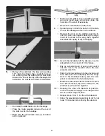
Page 9: ...in into the slots after again checking the align ment of the stab to the wing tape together and allow the epoxy to dry thoroughly 10 As with the installation of the ailerons insert a straight pin in the center of 6 CA hinges Mix up a small amount of epoxy and insert it into the hole in the elevator where the wire elevator joiner fits Slide the hinges halfway into the elevator and then slide the en...

Page 10: ... Nylon Control Horns with Base Plates 2 1 5mm x 20mm Machine Screws 2 1 5mm Metal Clevis 2 Silicone Clevis Keepers 4 Shrink Tubing 2 Position the control horn so that the metal cle vis holes are right next to the hinge line as shown 3 Using a 3 32 drill bit make a hole in each screw location Mount the rudder control horn using the 1 5 x 20mm machine screws base plates Place the silicon keeper over...

Page 11: ...l the e z connector on one end of the servo arm NOSE GEAR INSTALLATION 1 COLLECT THE FOLLOWING PARTS 1 Nose gear strut 3 Wheel Collars and set screws 1 Wheel 1 Nose gear steering arm 1 1 5mm x 43 cm wire and tube 1 EZ connector and screw 1 Nylon Swivel Keeper 2 Slide a wheel collar with a set screw onto the top of the nose gear gear strut 4 Insert the nose gear strut thru the hole on the bottom of...

Page 12: ...tate the nose gear around into position 8 Slide the nose gear wire into the hole in the EZ connector and center the servo arm and the nose gear wheel When satisfied tighten the set screw on the EZ connector ENGINE INSTALLATION 1 COLLECT THE FOLLOWING PARTS 1 ENGINE 6 6 X 3 4SHEET METAL SCREWS 3 MOTOR MOUNT PLATES 1 SPINNER 3 NOT INCLUDED 9 Install the nose gear with a wheel collar on each side 2 L...

Page 13: ...e ring Open the spinner and place the spinner back plate onto the engine This will help to center the front of the engine to the fuselage Make sure that there is a clearance between the spinner back plate and the front of the fuselage 4 Mark the location of the engine mounting holes Also at this time mark the location of where the throttle pushrod should exit the firewall Remove the engine and the...

Page 14: ...the engine throttle arm Hole 3 Make a notch in the bulkhead for the nylon tube to fit into THROTTLE PUSH ROD INSTALLATION 1 COLLECT THE FOLLOWING PARTS 1 1 5MM X 40CM 1 NYLON TUBE 1 NYLON CLEVIS notch 4 Place the EZ connector on the throttle servo arm just as you did earlier Slide the throttle pushrod through the EZ con nector and adjust as necessary 1 GATHER THE FOLLOWING ITEMS 1 FUEL TANK 1 RUBB...

Page 15: ...5 Install the assembly into the tank so the vent tube is turned up to the top of the tank and is positioned on the right side of the tank Tighten the screw to expand the rubber cap Don t over tighten or you could split the tank 6 Attach the two pieces of 5mm tubing to the two tank outlets Make a note of which one you attach to which tube The short brass with the clunk is the fuel pickup and must g...

Page 16: ...her with tape as shown 1 Tack glue the figure by applying a few drops of CA glue at key joint areas When dry remove tape and apply a small amount of glue all along the seam PAINT PILOT AS DESIRED Cut line Using artist s acrylics or modeling enamels paint the pilot to suit your fancy WARNING Do not use lacquer based paints which will destroy the plastic When dry CA glue the pilot in place on the co...

Page 17: ...nce stand until the model is level or the nose slight ly down If the is tail heavy shift the R C equipment away from the heavy end of the model and recheck until the model will balance within the acceptable range If shifting the R C gear still doesn t balance the model add weight to the far end of the nose or tail respectively until the model is correctly balanced The least weight is needed when a...

Page 18: ... power take off for a short 2 to 3 minute first flight Before the second flight take off the wing and check all screws radio equipment engine mounting muffler etc to make sure that nothing has come loose Spend the following flights getting famil iar with your model and making sure it is properly trimmed for straight and level flight When you feel comfortable with your model it s time to try aeroba...

Reviews: