12
90˚
90˚
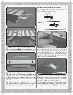
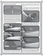
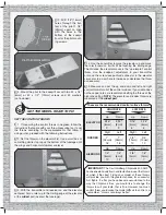
6. Connect the servos to your receiver and power up the
system with the trims on the transmitter centered. Fit the
servo arms on the servos so they will be as close to 90
degrees as possible to the pushrods (but they don’t have to
be perfect). Cut off the unused servo arms.
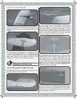
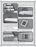
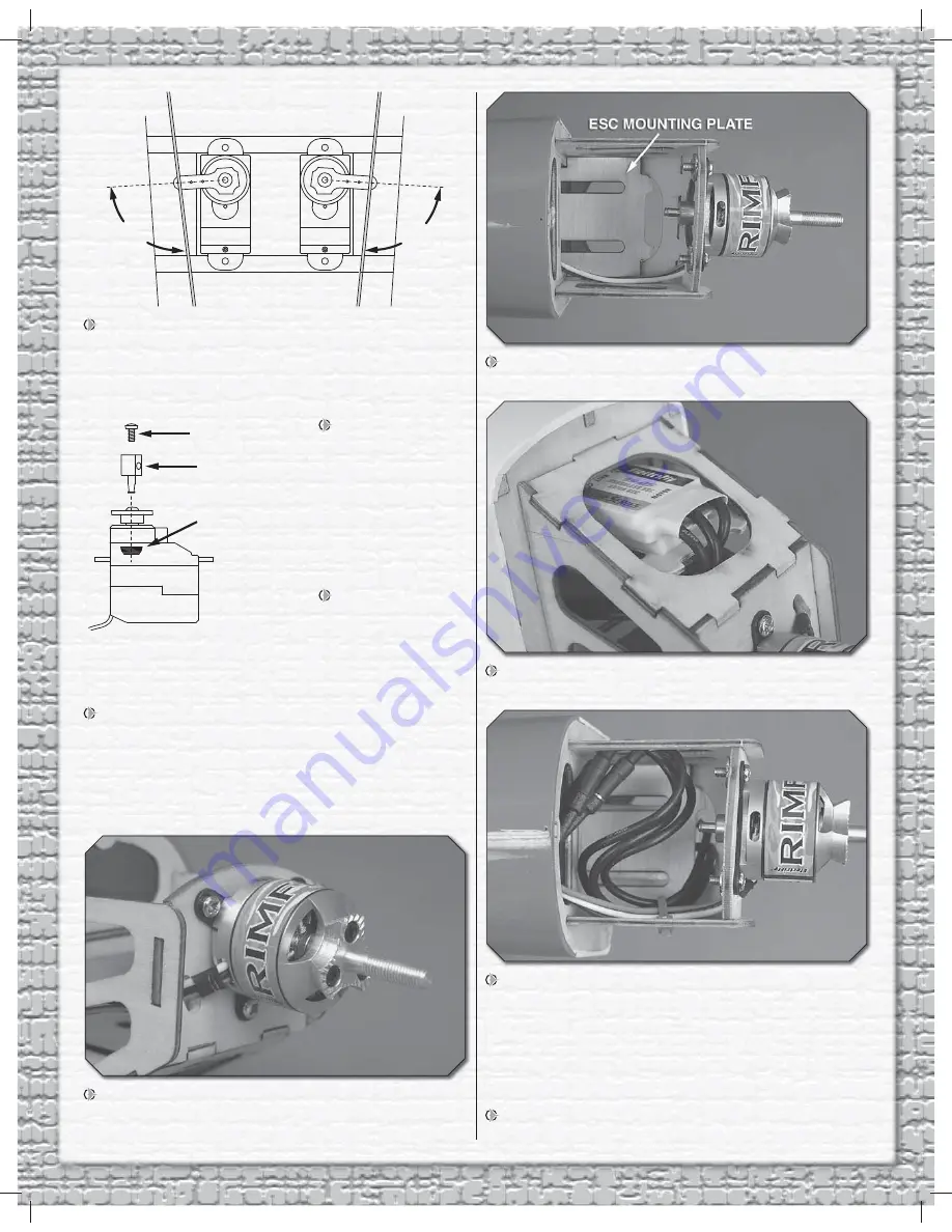
7. Use a #55 (.052"
[1.3mm]) drill or a
hobby knife to enlarge
the holes in the servo
arms. Then, mount a
screw-lock connector
to each arm using
the nylon retainer as
shown.
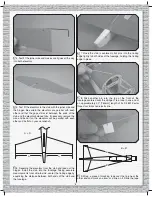
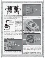
8. Fit the pushrods
into the screw-lock
connectors on the
servo arms. Position
the servo tray wherever the servos align with the pushrods.
Securely glue the servo tray into place.
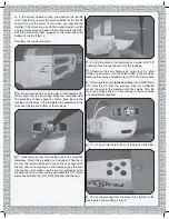
9. One last time, turn on your radio and power the
servos. Center the elevator and rudder. Next, add a drop
of threadlocker to the screws in the screw-lock connectors
and tighten them down. Cut the pushrods approximately 1/2"
[10mm] past the screw-locks.
MOUNT THE MOTOR AND ESC
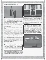
1. Guide the motor wires through the hole in the fi rewall
and mount the motor with three 3 x 8mm Phillips screws and
a drop of threadlocker on the threads.
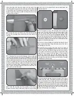
2. Fit, then glue the plywood
ESC mounting plate
into position.
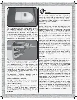
3. Mount the ESC to the ESC mounting plate with double-
side foam mounting tape (not included).
4. Using 3.5mm male bullet to 2.0mm female bullet
adapters (GPMM3122, not included), connect the ESC wires
to the motor wires, keeping as much of the wiring as you
can in front of the fuselage in the cowl area so it will not be
in the way of the battery—when installing the battery later, it
should be placed forward to reduce any nose ballast that will
be required to get the proper C.G.
5. Turn on the radio and connect the battery to momentarily
power up the system. Make certain the motor turns and does
SCREW
RETAINER
SCREW-LOCK
CONNECTOR


