background image

10

3.

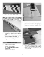
Draw a line across the hinge line of the rudder

and transfer the mark to the other side of the

rudder. 

Using a 1\8” drill, drill half way through the rud-

der from both sides  Complete the hole com-

pletely through the rudder.

4.

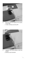
Install the 4-40 x 3-1/2” threaded rod in the hole

with a nylon washer and nylon nut on each side

Thread the nylon pushrod fitting on each end of

the rod.

5.

Mix some 30 minute epoxy and apply some in

the holes in the rudder and fin using a tooth pick

or piece of wire.

Apply a drop of oil to each hinge. Put a dab of 

glue on the end of each hinge and install. 

Fit the rudder in place and work back and forth 

several times to rotate the hinges in place. 

Use tape to hold the rudder in place till the glue

dries.

6.

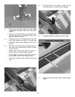
Use the four #2 x 1/2” screws to mount the tail

wheel bracket to the bottom of the fuselage.

7.

Install the tail wheel using the wheel collar.

MOUNTING STABILIZERS

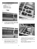
1.

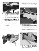
Insert the two aluminum tubes in the fuselage

sides.

Summary of Contents for Yak 54

Page 1: ...to use only those radio frequen cies specified for Model Aircraft LIMITED WARRANTY Carl Goldberg Products has inspected and certified the components of this aircraft The company urges the buyer to perform his own inspection prior to assembly and to immediately request a replacement of any parts he believes to be defective for their intended use The company warrants replacement of any such componen...

Page 2: ...ate servo mounting trays wing hold down blocks Firewall etc Also during the course of shipping from the manufacturer to our facility in the United States it is not uncommon for the aircraft to experience several changes in climate This may cause the iron on covering to develop wrinkles This is not a fault of the manu facturer Please take a few minutes with your heating iron and iron down the seams...

Page 3: ...d ed If CA does happen to get into the eye hold lid open and flush with water only Seek immediate medical atten tion CONSTRUCTION TIPS IMPORTANT ALWAYS READ A FEW STEPS AHEAD This will alert you to coming instructions and will help you plan accordingly COVERING The 67 Yak 54 ARF is covered in a premium polyester film chosen by many of the world s top flyers for its beau ty toughness and ease of ap...

Page 4: ...ustable control horn onto the bolt Note Thread the side that you can see the cut threads in the nylon onto the bolt 2 With the aileron servo in place make a mark on the aileron at a 90º degree angle to the trailing edge and in line with the servo Look for the control horn hard point under the cov ering This is the location for the control horn 4 AILERON CONTROL HORN INSTALLATION 1 Collect the foll...

Page 5: ...sing a piece of wire or a toothpick work some epoxy into each hole on the wing and aileron Working with 1 hinge at a time place a dab of epoxy and insert the hinge half way into one of the aileron holes Repeat for each of the other hinges for that aileron 5 Working quickly place some epoxy on the second half of each hinge and insert the aileron into the wing Slide the aileron toward the wing until...

Page 6: ...ng till it exits the root rib 5 Tape the end of the plug to the root rib Repeat for the other wing half Aileron Servos Pushrods 1 Collect the following items 2 nylon swing in keepers 2 2 56 pushrods threaded one end 2 2 56 clevis 2 silicone clevis retainers 2 Slide the silicone keeper on the clevis Screw the 2 56 pushrod into the clevis so 1 16 of threads extend past the opening Attach the clevis ...

Page 7: ...7 4 Bend the pushrod 90 degrees at the location of your mark Cut the remaining wire leaving 3 8 3 8 5 Install the nylon swing in keeper to attach the pushrod Repeat for the other aileron ...

Page 8: ... axle to the landing gears 8 FUSELAGE HATCH The top front half of the fuselage is a hatch Remove the 4 40 socket head bolts on the side of the fuse lage to disengage the hatch 2 Insert the gear legs through the slots in the fuselage side Use the six 6 32 x 1 bolts to secure the gear The blind nuts are already installed in the fuselage The bolts install from the inside of the fuselage Be sure and u...

Page 9: ...e the rudder four hinges and the tail wheel bracket Use the 3 6 drill and drill each hinge hole 1 8 deep so the shoulder of the hinge will fit into the hole up to the hinge pin Do the same on the hinge holes on the fin Fit the tail wheel bracket in place 2 Trial fit the rudder in place on the fin Make sure the hinge line is tight and the counter bal ance does not rub on the top of the fin Align a ...

Page 10: ...the rod 5 Mix some 30 minute epoxy and apply some in the holes in the rudder and fin using a tooth pick or piece of wire Apply a drop of oil to each hinge Put a dab of glue on the end of each hinge and install Fit the rudder in place and work back and forth several times to rotate the hinges in place Use tape to hold the rudder in place till the glue dries 6 Use the four 2 x 1 2 screws to mount th...

Page 11: ...is mark to the other side of the stab Using a 1 8 drill drill the hole for the control horn 5 Install the 4 40x3 bolt nylon washer nylon nut and tighten down Install the pushrod fitting on the end Repeat for the other elevator 6 Hinge the elevators in place using the same method we did on the ailerons and rudder HINT Drill the hole from the bottom half way Then measure and mark the top of the aile...

Page 12: ... fuselage 3 Slide the silicone clevis keeper on the clevis Screw the clevis on the pushrod till the threads extend past the end 1 16 Attach the clevis to the elevator control horn 4 Install the servos in the servo tray as shown 5 Install your control horns You will need heavy duty long horns 1 to get full 3 D throw Make sure the elevator is centered and the servo is centered Mark the location of t...

Page 13: ...d to prevent binding Operate the servo using your radio and bend till there is no binding 7 Repeat for the other elevator servo Rudder Servo Installation 1 Collect the following parts 2 2 56 clevis 2 silicon clevis keepers 2 rigging couplers 4 brass cable swages 6 1 2 braided cable 2 Take the end of the braided cable and thread through one of the brass cable swages then through one of the rigging ...

Page 14: ...e servo and measure to see if this is about half the cable Adjust till the cable is equal lengths and cut into two pieces 6 Repeat for the other side 7 Install the rudder servo in the center slot of servo tray 8 You will need a heavy duty double sided con trol arm Tape the rudder in the neutral position Make sure the rudder servo is centered Thread each cable through one of the swages through the ...

Page 15: ...re at any time so inspec tions must be thorough We will not warranty any structural failures do to neglect or accidents 1 You will find both the horizontal and vertical lines marked on the firewall The vertical line is off set to compensate for the 2 degrees right thrust Mark your motor mount location from these marks The front of the cowl is 6 from the firewall Caution Always use thread lock on a...

Page 16: ... firewall Drill a 25 64 hole at the four locations 4 Using the 3mm mounting bolt and washer pull the blind nuts into the firewall 5 Mount the engine using the four 3mm x 25mm screws and flat washers Be sure and use thread lock on the bolts Cowl Mounting 1 Collect the following items 1 cowl 4 4 40 x 1 2 screws 4 nylon cup washers 2 Take four strips of paper Not Included and tape to the side of the ...

Page 17: ... the location of the mount ing holes from the paper to the cowl Remove the cowl and drill a 1 8 hole at the four locations 5 To locate the needle valve outlet hole tape a piece of paper to the side of the fuselage with the needle valve extension through the paper 6 Remove the needle valve Reinstall the cowl using the bolts and transfer the hole location to the cowl Remove the cowl and drill a 1 4 ...

Page 18: ...ane depending on the engine you use Mount the servo so it will be on the same side of the plane as your throttle arm on the engine 4 Drill a hole 1 4 in the motor box that will give you the most direct access to the servo This will vary depending on the engine used Make sure it will clear the tank inside Thread the nylon snap link on the pushrod insert the pushrod in the nylon tube and fit into th...

Page 19: ...throttle and tighten the screw on top of ez connector Cut off excess pushrod wire Fuel Tank Installation 1 Collect the following items 1 fuel tank 1 cap assembly 1 clunk 1 pick up tube 3 aluminum tubes 2 Insert the three aluminum tubes into the cap assembly There should be two short tubes that extend out the front and back of the cap about 1 2 to 5 8 The third line is the vent and should be bent a...

Page 20: ...can be glued the the fuselage sides and the tank tray glued to the rails This shows the tank mount in the forward position 7 The tank mount can be slid to the rear of the compartment and glued in place to get the tank closer to the CG You will need an engine with a fuel pump to move the tank to the rear position 8 Install the tank with the cap through the hole in the firewall and sitting in the cr...

Page 21: ...sing the two 4 40 x 1 2 screws Put a piece of wax paper between the tur tledeck and canopy bulkhead to prevent glue from getting in the seam Put a bead of canopy glue around the edge of the canopy on the inside and fit into place Make sure canopy is properly positioned and hold in place with masking tape till glue dries Most canopy glues can be cleaned up with water while still wet Check the glue ...

Page 22: ...full length you will probably want to cut them down to about 3 4 to 1 to make them easier to install 3 Install the battery pack according to where you need the weight to make the CG correct With all equipment installed check the CG Control Throws and CG Ailerons Low Rate 3 4 each direction High Rate 1 1 2 each direction Elevators Low Rate 1 1 4 each direction High Rate 3 each direction Rudder Low ...

Reviews: