Technical Data
Dynacode II Series
24
Operating Manual
08.16
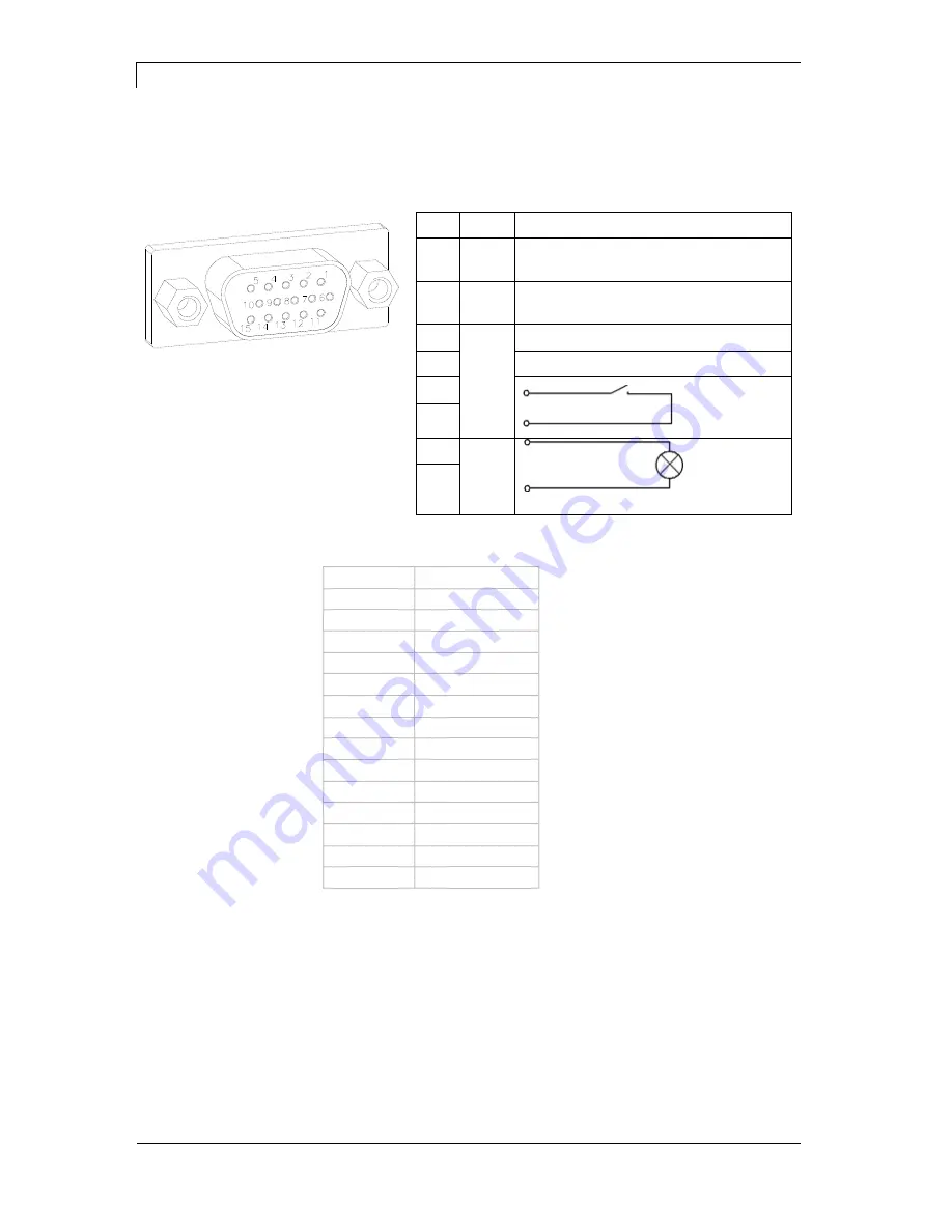
External bushing I/O-24
Figure 7, D
This input is executed as 15-pole and provides user-sided
24V/100mA.
In case of using this bushing, exists
no galvanic
separation
.
Figure 13
PIN
Port
Function
1,
6
Gnd
5,
10
24 V / 100 mA
3
1
Print start (NPN initiator)
2
Print start (PNP initiator)
4
Print start by
potential-
free contact
14
7
9
Signal lamp
24 V / 100
mA
(error)
13
PIN 1
white
PIN 2
brown
PIN 3
green
PIN 4
yellow
PIN 5
grey
PIN 6
pink
PIN 7
blue
PIN 8
red
PIN 9
black
PIN 10
purple
PIN 11
grey-pink
PIN 12
red-blue
PIN 13
white-green
PIN 14
brown-green
PIN 15
free
Pin assignment for
connecting cable
External bushing I/O-24


