Technical Data
Dynacode II Series
32
Operating Manual
08.16
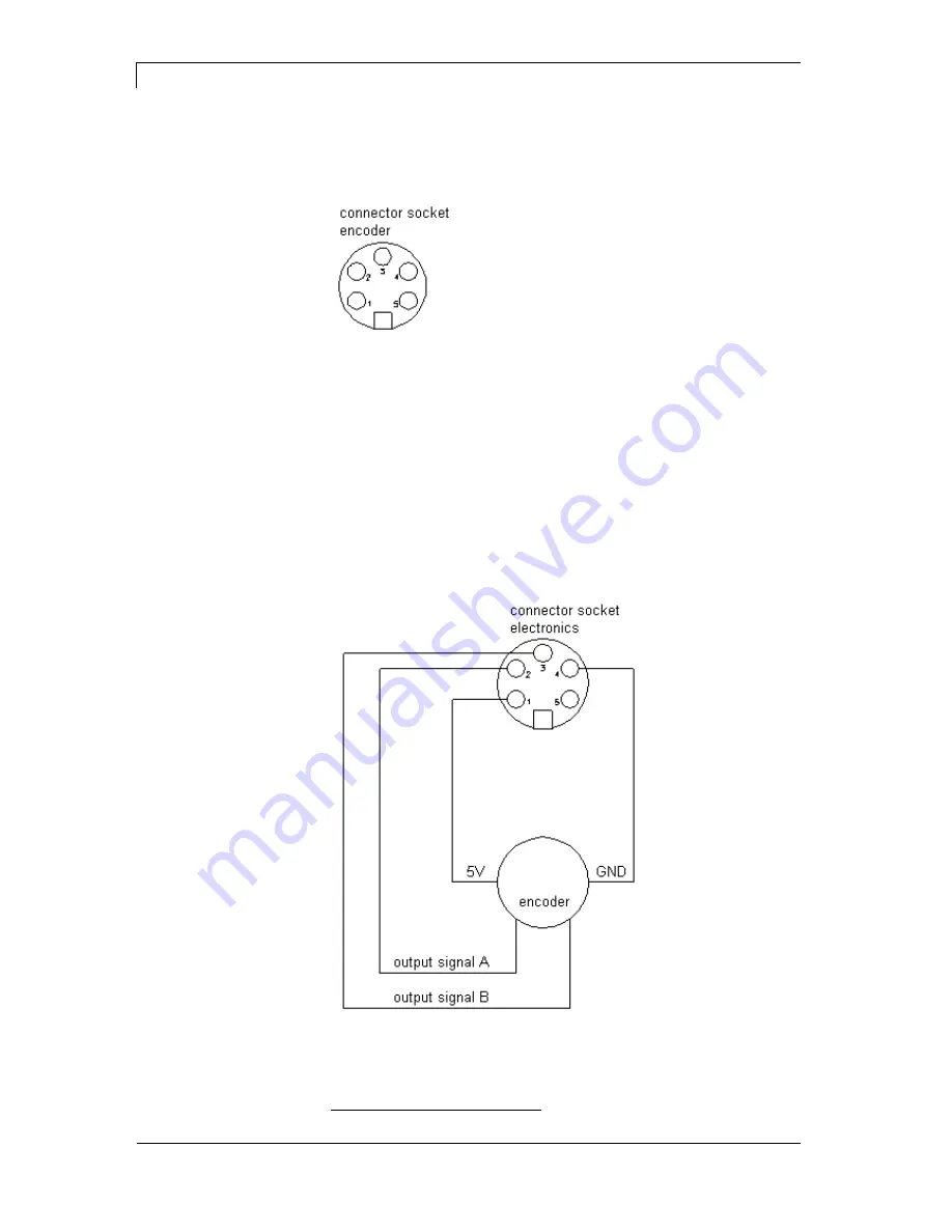
6.4 Pin Assignment of Encoder Socket
5-pin connecting bushing, contacts according to DIN 45322
Figure 24
PIN1 = 5 VDC
PIN2 = Encoder signal (channel A)
PIN3 = Encoder signal (channel B)
PIN4 = GND
Operating voltage:
5 VDC
Output signal:
TTL level
Resolution:
Can be set at the print module
Figure 25
only for continuous mode
Electrical data of
encoder
Connection of encoder


