Flexicode
Technical Data
11.19
Operating Manual
29
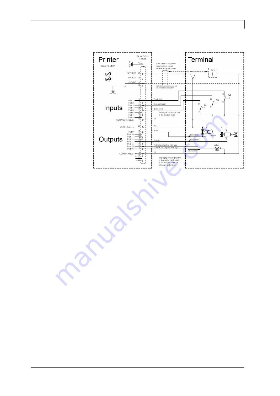
Device connection version if 'Option: 2. LED'.
Figure 12
When connecting a reed contact with a control input, the contact must
have a switching capacity of min. 1 A in order to prevent the contact
from sticking due to the inrush current. As an alternative, a suitable
resistor can be connected in series.
If one of the printer’s internal voltages '+5 VDC EXT' or '+24 VDC
EXT' is used, an external fuse e.g. 0.5 AF, should be additionally
installed to protect the printer electronics.
In the event of an inductive load, an antiparallel connected diode, for
instance, must be used to discharge the induction energy.
In order to minimise the influence of leakage currents at control
outputs, a resistor must, depending on what is connected, be installed
in parallel with the load.
In order to avoid any damages to the printing system, the max. output
currents must not be exceeded or outputs shorted.
Example 3
Precautions
Summary of Contents for FLEXICODE 53
Page 1: ...FLEXICODE Operating Manual ...
Page 8: ...Introduction Flexicode 8 Operating Manual 11 19 ...
Page 14: ...Machine Overview Flexicode 14 Operating Manual 11 19 ...
Page 18: ...Operating Conditions Flexicode 18 Operating Manual 11 19 ...
Page 40: ...Installation and Initial Operation Flexicode 40 Operating Manual 11 19 ...
Page 44: ...Operation Panel Flexicode 44 Operating Manual 11 19 ...
Page 94: ...Maintenance and Cleaning Flexicode 94 Operating Manual 11 19 ...
Page 100: ...Signal Diagrams Flexicode 100 Operating Manual 11 19 ...
Page 114: ...Additional Information Flexicode 114 Operating Manual 11 19 ...
Page 116: ...Environmentally Friendly Disposal Flexicode 116 Operating Manual 11 19 ...


